


1. Introduction
Historically, material technologies have profoundly influenced the human civilization, and hence, historians have defined distinct time periods by the dominant materials used during these eras. It is known that the term smart materials first appeared in the late 1980s, and since then numerous research activities on smart materials have been or are being performed in diverse industry areas. Among the many inherent characteristics of smart materials, the crucial common denominators to achieve high performances in application systems are their capabilities of sensing, actuating, and controlling under external stimuli that govern the responses of the systems. To date, more than a hundred types of smart materials with those capabilities have been proposed and their adaptability as “smart” has been validated. This includes the identification of material characteristics showing sensitivity as a sensor, generating force as an actuator, and performing control response as a controller. In the last two decades, several class of smart materials has drawn significant attention in a broad range of engineering applications because of their unique and useful actuator properties. Potential smart materials with actuator properties include electro-rheological (ER) fluids, magneto-rheological (MR) fluids, shape memory alloys (SMAs), piezoelectric transducers, magnetorestrictive materials, and electro active polymers (EAPs).
In the robotic research society, many researchers have developed various types of robots using traditional actuators (e.g., electric motors, hydraulic fluidic actuators) to achieve some specific requirements for desired movements. Although some robots with conventional actuators exhibit excellent performance, alternative actuators need to be explored when the capability to perform flexible and complex movements is required. Smart material-based actuators are one of the alternative solutions because of their relatively small weight and volume, compared to those fabricated using conventional actuating methods. For example, SMAs have been widely used in a diverse range of humanoid robotic applications since the 1980s, especially as artificial muscles, because SMA wire actuators can mimic the human muscle. In fact, the use of smart materials as actuators can be categorized into in terms of their application area, such as automotive, aerospace, robotics, and biomedical. Despite numerous research works on the smart materials applications, a comprehensive overview on the specific application area has not been reported yet. Therefore, it is worthwhile, as a first step, to review the robotic application using smart materials.
Consequently, the main objective of this review article is to present a broad perspective of the research efforts during the last decade in relation to robotic applications and their prototypes based on smart materials. This review describes the attributes of specific smart materials that make them ideal for actuating robotic applications, and discusses their associated technical capabilities and limitations in order to emphasize the design challenges. This review paper also provides an updated review of recent smart material researches for robotic applications, with over a hundred state-of-the-art references categorized into types of smart materials. However, specialized topics such as modeling and mechanics of smart materials will not be discussed in details in this article. Although this work focuses on an extensive review of robotic applications using smart materials, other contents are also presented including a brief overview of smart material properties, a summary of recent advances, and new application opportunities.
2. Piezoelectric Materials
2.1 Property overview
Piezoelectricity is a material property that is observed as an electric charge or voltage produced by applied mechanical forces, or, conversely, as a mechanical deformation caused by an applied electric field. The first experiment displaying the piezoelectric effect was performed on some special crystals, such as quartz, topaz, tourmaline, cane sugar and salt, and the results were published by Pierre and Jacques Curie in 1880. The crystals were subjected to a mechanical stress and a conclusive measurement of surface charge was made, and this discovery was named piezoelectricity. In 1881, converse piezoelectricity was mathematically proved by Limppman and confirmed by the Curies. After great efforts to make ceramic materials with high piezoelectric properties, lead metaniobate (PMN) and lead zerconate titanate (PZT) were developed, and these two materials are still the most widely used piezoelectric materials. In addition, the strong piezoelectric effect in piezovinylidene fluoride (PVDF) was first discovered by Kawai in 1969 and this piezoelectric polymer is also still heavily used in various smart structures. Piezoelectric materials are available in the form of stacks, where many layers of materials and electrodes are assembled together. These stacks generate large forces but small displacements in the direction normal to the top and bottom surfaces. However, due to the ceramic nature of the monolithic piezoelectric material, they are very brittle and accidental breakage could occur during handling and bonding procedures. In addition, they are not easily attached to curved surfaces. Furthermore, they are very dense and stiff, and mass loading and localized stiffness could be caused when working with very flexible or lightweight structures.
To resolve those limitations, the idea of using a composite material consisting of an active piezoceramic fibrous phase embedded in a polymeric matrix phase was investigated, and the Macro-Fiber Composite (MFC) was developed. Chopra reviewed the status of smart structures and integrated systems and summarized the general material properties and modeling method of structures with piezoelectric materials [1]. Crawley and de Luis provided a pioneering work in this area, involving the development of the induced strain actuation mechanism [2]. Crawley and de Luis developed a model of the mechanical coupling of bonded piezoelectric actuators to the dynamics of the structural member. Bimorphs type actuators are most widely used, where two layers of piezoelectric elements are stacked with a thin structure between them. If an opposite polarity is applied to two sheets, a bending action can be created. Bimorphs cause a larger displacement and smaller force as compared to the single piezoelectric element. The typical advantages of a piezoelectric actuator are linear output to input voltage, fast response, wide operating frequency range, high actuating force per unit volume, and low power consumption. The scope of this review is focused on robot applications of piezoelectric actuators.
2.2 Piezoactuator-Based Robots
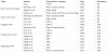
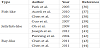
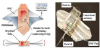
The piezoelectric robot research works can be classified as robot arm and finger, inchworm robot, underwater robot legged robot, and flying robot. They are summarized in Table 1. The early research on piezoelectric robots was focused on control of the robot arm and manipulator. In 1989, Tzou developed a lightweight robot endeffector using a bimorph structure based on a PVDF material [3]. Depending on the applied voltage, the effector could hold an object from outside or inside. The theoretical prediction was verified with the experimental and finite element simulation results. This endeffector can be used for pick up lightweight objects, such as electronic chips. Varadan et al. proposed a lightweight robot using a piezoelectric motor and a piezoelectric ceramic actuator [4]. The piezoelectric sensor and actuator were attached on the surface of the lightweight flexible arm, and the piezoelectric motor was designed and installed as a quick response driver of the robotic arm. The diameter of the piezoelectric motor was 40 mm, with a maximum speed of 520 r/min and a maximum torque of 0.07 Nm. The total weight of the manipulator was only approximately 0.1 kg. Fatikow et al. developed three different piezoelectric micro-manipulation robots [5]. First, a one-leg robot was designed as a positioning unit by using a stacked piezoelectric actuator. A three-leg robot, called SPIDER-1, was also designed as a positioning unit by using bimorph-type piezoelectric ceramic actuators. Finally, a manipulator driven by three piezoceramic actuators was designed. The bimorphic actuator that is fastened to the robot’s body was used to raise and lower the manipulator arm, while the other two actuators work as a two-fingered gripper. Zhang et al. proposed a robot finger involving two joints with four DOF, based on two hybrid multi-DOF piezoelectric ultrasonic motors [6]. The motor’s stator was assembled by a multi-layered piezoelectric vibrator for longitudinal motion and a sandwich type bending vibrator. The multi-layered vibrator can produce a large longitudinal vibration velocity in the z direction at low driving voltage. The sandwiched vibrator, composed of two PZT rings and four divided bronze electrodes, can excite the bending vibration in two orthogonal directions under phased voltages. By combining the longitudinal and bending vibrations, rotation of the ball rotor can be generated in three directions. This method is illustrated in Figure 1.
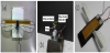
Many research works have been conducted for inchworm type robots driven by a piezoelectric actuator. Holinger and Briscoe carried out an optimization, based on a genetic algorithm and numerical performance evaluation, for a piezoelectric pipe-crawling inspection robot [7]. The proposed design used piezoelectric expansion actuators to move the robot with the 'chimneying' method employed by mountain climbers, and greatly improved on previous designs in load bearing ability, pipe traversing specifications, and field usability. The optimization was performed for total mass, power consumption, and joint extension, and then the robot design parameters were obtained. After optimization for power consumption, the center extension was increased from 3.0 mm for the initial configuration to 5.0 mm for the optimized configuration. However, the power consumption was decreased from 1514 W for the initial configuration to 584 W for the optimized configuration. Yan et al. developed a miniature-step mobile robot with 3-DOF driven by a piezoelectric actuator [8]. By utilizing a rhombic flexure hinge mechanism and four electromagnetic legs, large stroke translation and rotation with high resolution was achieved. The assembled mobile robot is presented in Figure 2.
In the last decades, many types of walking robots activated by piezoelectric actuators were proposed and developed. Lee et al. proposed a cockroach-inspired six-legged hexapod robot, which uses a lightweight piezoceramic composite curved actuator (LIPCA) [9]. The fabricated robot is presented in Figure 3(a). The maximum speed of the proposed robot reached 170 mm/s at 40 Hz by applying an input voltage of 400 Vpp. Ho et al. also developed a quadruped mobile robot that employs two pieces of LIPCA actuators for bounding locomotion [10]. The design of the robot leg is inspired by legged insects and animals, and the biomimetic concept is implemented in the robot. The manufactured robot is presented in Figure 3(b). The maximum payload of the bounding prototype was found to be approximately 100 g. The bounding prototype has the ability to carry an additional load, up to 100 g, at a speed of 67 mm/s. Song and Sitti developed a biologically inspired miniature water strider robot driven by the surface tension force [11]. To support the weight of the robot, optimized hydrophobic Teflon coated wire legs were adopted by taking the advantage of the surface tension force. A T-shape actuation mechanism, with three piezoelectric unimorph actuators, was designed to control the locomotion. The maximum forward speed obtained was 30 mm/s, and the rotational speed was 0.5 rad/s.
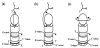
Research works for biomimetic underwater robots have been carried out by many researchers, utilizing various piezoelectric actuators. Goo et al. proposed a biomimetic fish robot actuated by a LIPCA [12,13]. The limited bending displacement produced by a LIPCA was amplified and transformed into a large tail beat motion by using a linkage system. The fully assembled biomimetic fish robot was 270 mm long, 50 mm wide, and 65 mm high, with a total mass of 550 g including a dummy weight of 450 g. From the experimental results, and by adopting a variable thickness caudal fin, the swimming speed reached 25 mm/s at 0.9 Hz with applied input voltage of 300 Vpp. Zhao et al. developed a soft underwater robot by mimicking a cow nosed ray, based on MFC actuators [14]. The fabricated fish robot structure is presented in Figure 4. The size of the proposed robot body was 110 mm long, 230 mm width, and the tail length was 20 mm long. The swimming speed of the manufactured robot, increased by rising the frequency of the input rectangular wave, was 53 mm/s at 1 Hz and 200 mm/s at 10 Hz. Aiguo et al. also developed a snakelike underwater robot as shown in Figure 5 [15]. The whole length of the robot was 130 mm and the maximum swimming speed reached approximately 500 mm/s at 35 Hz square wave, with applied input voltage from -500 to 1500 V.
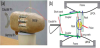
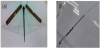
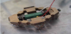
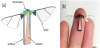
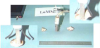
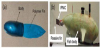
Because the piezoelectric actuator has the inherent advantage of high actuating force per unit volume, many research works have been undertaken to develop a flapping wing for flying robots. In 2009, Ming et al. developed an active flapping wing with MFC actuators and investigated its characteristics through experiments [16]. The prototype of the proposed flapping wing is presented in Figure 6(a). The weight, area, and span of one side single wing were 2.25 g, 4200 mm2 and 297 mm, respectively. The resonance frequency was 16 Hz. The lift and thrust forces were experimentally measured according to the attack angle. From the results, the maximum mean lift reached 28.5 mN at the attack angle of 60° and the maximum mean thrust was 7.35 mN at the attack angle of 10°. Fukushima et al. proposed a new type of flapping robot with a ring-shaped driving module, inspired from insects with an indirect flight muscle, as shown in Figure 6(b) [17]. The ring was made of carbon plate and the weight, including the hinge mechanism and ring-shaped module, was 4 g. The mean lift and mean thrust forces were experimentally measured according to the wing type and length. The maximum mean lift was 0.94 mN with a Rhagionidae type, 60 mm length wing, while the maximum thrust reached 1.09 mN with a Rhagionidae type, 30 mm length wing. In 2012, Ming et al. improved the performance of their flapping robot by adopting a new flapping mechanism inspired from insects with indirect flight muscles [18]. The flapping robot prototype is presented in Figure 6(c). They designed the driving module by using two double-end supporting beams made of carbon fiber reinforced polymer (CFRP) with a surface-bonded MFC actuator. The mean lift and meat thrust forces reached 36.67 mN and 37.48 mN, respectively. In addition, compared to the previous ring-shaped module, the ratio of lift to weight increased from 0.0157 to 0.9355 and the ratio of thrust to weight increased from 0.0686 to 0.956, approaching to 1. Wood developed a biologically inspired flying-insect robot with a piezoelectric actuator and evaluated its performance through experiments [19]. The schematics and photograph of the proposed micro robot is presented in Figure 7. The total mass was 60 mg with a wing span of 30 mm. The maximum wing velocity was 6 m/s and the resonant frequency was 110 Hz. From the experimental results, the average lift was 1.14 mN and the ratio of thrust to weight was approximately 2.
3. Electroactive Polymers
3.1 Property overview
For decades, attention has been focused on polymer actuators for the design and control of smart systems. Electroactive polymer (EAP) is a kind of active polymer that can produce a significant shape change in response to external electrical stimulation. The EAP has attractive properties, being flexible, lightweight, and soft compared with other smart materials. There are many different types of EAPs and they can be classified into two categories according to their activation mechanisms, electronic EAPs and ionic EAPs. Electronic EAPs, such as dielectric elastomers (DEs) and liquid crystal elastomers (LCEs), are driven by electric field or Maxwell forces. These EAPs have fast response time and high mechanical energy density. In addition, they can generate a large actuating force under high voltage input (higher than 100 V). Since electronic EAPs can be made to hold the induced strain under activation of a certain DC voltage input, they can be used in robotic applications. However, they have mostly mono-polar actuating because of electrostriction effect caused by independence of the voltage polarity. On the other hand, ionic EAPs, such as conductive polymers (CPs) and ionic polymer metallic composites (IPMCs), are driven by the ionic movements (diffusion of ions) and they can be activated by a low voltage input (1 or 2 V). These EAPs has inherent bi-directional actuation that depends on the voltage polarity. The significant disadvantage of Ionic EAPs is that they require encapsulation or protective layer to operate in open-air condition. Moreover, they have low electro-mechanical coupling efficiency and slow response time. The advantages and disadvantages of the different EAPs have been well addressed in [20-22].
3.2 Property overview
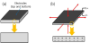
DE is the representative material among electronic EAPs, and has been used as actuator in robot applications because of its large deformation ability, high force density, and cost-effectiveness [23]. DE actuators consist of a thin elastomeric film covered on both sides with electrodes. The basic operating principle of a DE is presented in Figure 8. By applying an electric field across the electrodes, an electrostatic attraction between opposite charges on opposite electrodes and a repulsive force between equal charges on each electrode are generated. Those forces contract the elastomeric film in the thickness direction and expand it in the in-plane direction. The typical operating voltage for DE films 10–100 μm in thickness ranges from 0.5 to 10 kV [24]. Because DE has an inherent electrostatic characteristic, power is consumed during thickness reduction and, theoretically, the deformed state can be maintained without additional power consumption.
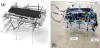
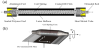
The first application of a dielectric elastomer actuator in robots was for artificial muscles. Kwak et al. reported about a face robot actuated with artificial muscles based on a dielectric elastomer in 2005 [25]. To generate six fundamental facial expressions of surprise, fear, disgust, anger, happiness, and sadness, seven actuator modules for the eye, eyebrow, eyelid, brow, cheek, jaw, and neck were incorporated in the robot. In this facial robot, each actuator module communicated with the other modules via the CAN (control area network) communication protocol, and facial motions were generated according to the desired emotional expression by combining the motions of each actuator module. A prototype robot was constructed and the feasibility was validated through several experimental results. The most representative feature of the proposed method over other face robots is its embedded and multiple DOF actuation. Kovacs et al. participated that the first arm wrestling match between a human and a robotic arm driven by EAPs was held at the Electroactive Polymer Actuators and Device (EAPAD) conference in 2005, and they reported on the entire development process of the robot in 2007 [26]. They proposed a spring roll actuator to achieve large actuating force with dielectric elastomers as shown in Figure 9. The actuator consisted of a bi-directionally pre-stretched and double-side-coated dielectric film wrapped around an elastic coil spring. The actuator elongated in in the axial direction and contracted back to its original length when an electric voltage was and was not applied, respectively. With the proposed actuator, elongation and generated force were up to 26% and 15 N, respectively. Based on the calculated stress condition in the rolled actuator, a low number of pre-strained dielectric elastomer film wrappings were preferable for achieving the best actuator performance. Because of the limited space inside the robot body, 256 rolled actuators with diameter of 12 mm were arranged in two groups, according to the human agonist–antagonist muscle configuration, in order to achieve an arm-like bidirectional rotation movement as shown in Figure 10. The rotary motion of the arm was activated and deactivated electrically by the corresponding actuator groups. The developed arm wrestling robot was made of a carbon fiber composite as shown in Figure 11. Although the robot lost the arm wrestling contest against the human opponent, the dielectric elastomer actuators demonstrated a promising performance as artificial muscles.


Various configurations of dielectric elastomer-based actuators have been proposed and designed, such as roll extended folded and stacked [27-29]. Choi et al. proposed a new design of a multi-jointed robot finger driven by an artificial muscle actuator and evaluated its control performance through an experimental test [30]. They proposed a new type of multi-stacked actuator that could generate linear motion like natural muscles. To transfer the linear motion into rotational motion, a simple slider crank mechanism was adopted. The manufactured prototype of the multi-joint robot finger and the movement of the proposed finger are presented in Figure 12. To control the motion of the proposed robot finger, a PWM-PID feedback controller was designed based on a high-voltage switching circuit and implemented to the system. Nguyen et al. also designed a small biomimetic quadruped robot driven by multi-stacked dielectric elastomer actuators [31]. A miniature legged robot driven by a biomimetic actuation system with four 2-DOF leg mechanisms was realized and the feasibility of the dielectric elastomer actuator for a locomotion mechanism was verified by replacing conventional actuators. The walking motion of the proposed robot is illustrated in Figure 13. The total size of the robot was 191 mm, 100 mm, and 115 mm of length, width, and height, respectively. The total weight, excluding and including the weight of the actuators, was 243 g and 450 g, respectively. They compared the performance of the proposed leg with the leg using a 3-DOF rolled dielectric elastomer actuator through numerical simulation and an experimental test and obtained a similar performance, with maximum angle of the leg of 20°–35°, by applying a driving voltage of 0–5 kV [32].
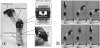

Among the ionic EAPs, IPMC is an excellent material for use as a smart actuator, which can be used for robot applications. When an external electric input is applied, a mechanical bending deformation occurs because of a change in the chemical structure. This makes the IPMC material to behave as a biological muscle, and thus, IPMC can be used as an actuator. IPMC consists of a polymer and electrodes and its structural configuration is presented in Figure 14. When an electric voltage is applied to the electrodes, an electrostatic attraction between the cationic counter ions and the cathode of the applied electric field occurs and the internal volume of water molecules will be unevenly distributed, resulting in a bending effect [33,34]. The advantages of the IPMC material are its large strain at low driving voltages, lightweight structure, bio-compatibility, flexibility, and silent actuation. The disadvantages of the IPMC material are its small generated force and the loss of water molecules while working in air condition, which limits the application environment if the loss of water molecules inside the material is limited. Bar-Cohen et al. designed and manufactured a human hand-like robotic arm with four fingers made of IPMC [35]. To increase the grasping force, hooks are designed at the end of the fingers, representing the concept of human finger nails. The manufactured robotic arm is presented in Figure 15. The gripper was able to lift 10.3 g of mass under a 5 V square wave signal at a frequency of 0.1 Hz.
The most common application of IPMC is in underwater swimming robots. The underwater swimming robots can be classified into three groups: Fish-like, ray-like, and jellyfish robots. The recent research for underwater robots using IPMC is summarized in Table 2. Kim et al. developed a wireless undulatory tadpole robot using IPMC actuators [36]. A biomimetic undulatory motion of a fin tail is implemented to improve the thrust of the tadpole robot. By changing the frequency and duty ratio of the input voltage, the motion of the tadpole robot is effectively controlled. Its structural configurations are presented in Figure 16(a). Aureli et al. developed a fish-like robot which is propelled by a vibrating IPMC with a size of 130 mm, 35 mm, and 45 mm of length, width, and height, respectively [37]. The time-varying actions actuated by the vibrating IPMC, such as thrust, lift, and moment, were estimated by combining force and vibration measurements with reduced order modeling based on modal analysis. The model predictions were validated through experimental results on a miniature remotely controlled fish-like robot. Chen et al. developed an autonomous fish-like robot propelled by an IPMC actuator [38]. Inspired by the biological fin structure, a passive plastic fin is attached to the IPMC beam. The structural configurations are presented in Figure 16(b).
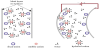
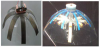
By mimicking the jellyfish motion, many kinds of jellyfish type swimming robots were developed using IPMC actuators. Guo et al. developed a new jellyfish t-like swimming robot that imitated the motion of jellyfish [39]. The process of floating and sinking was controlled by the applied input voltage. Four legs with IPMC actuators were designed to replace the antennae of the jellyfish. The moving speed was controlled by changing the frequency of the input voltage. Yeom et al. developed a biomimetic jellyfish robot based on IPMC actuators [40]. The fabricated structure is presented in Figure 17(a). The curved shape of the IPMC actuator through thermal treatments was successfully applied to mimic the real biomimetic robots with smooth curves. In order to obtain large vertical floating displacement and high Thrust force of the biomimetic jellyfish robot, a bio-inspired electrical input signal with pulse-recovery process was adopted. The maximum experimental frequency of the actuator was 16.6 Hz and its maximum speed at 1 Hz was 2.3 mm/s. Joseph et al. designed and fabricated a biomimetic jellyfish robot that used IPMCs as flexible actuators for propulsion [41]. The shape and swimming style of this underwater vehicle were based on the Aequorea victoria jellyfish because both its bell morphology and kinematic properties matched. the mechanical properties of IPMC actuators. The fabricated structure is presented in Figure 17 (b). The jellyfish type robot with four actuators swam at an average speed 0.77 mm/s and consumed 0.7 W. When eight actuators were used, the average speed increased to 1.5 mm/s with a power consumption of 1.14 W. Punning et al. developed a ray-like underwater robot in 2004 [42] as shown in Figure 18.” In this study, the pectoral fin of a ray was mimicked and 12 IPMC were installed. By adopting a sequential control of the IPMCs, the maximum speed reached 0.005 mm/s at a wave frequency of 0.4 Hz. The Chen et al. developed a robotic cownose ray by using an IPMC actuator and PDMS [43]. The size of the robot was 210 mm, 330 mm, and 50 mm of length, width, and thickness, respectively. Its maximum speed was 7 mm/s at a frequency of 0.157 Hz. Chen et al. also developed a pectoral-fin-mimicking a manta-ray, which consisted of a PDMS membrane using four IPMCs [44]. Through their experiments, the maximum tip deflection of the actuator was 17.5 mm and the maximum speed was 4.4 mm/s at 0.4 Hz.
4. Conclusion
This topical review presents state-of-the-art developments of robotic applications using smart materials. Smart materials used for robotic applications include electro-rheological (ER) fluids, magnetorheological (MR) fluids, shape memory alloys (SMAs), piezoelectric transducers, among others. Smart fluids still have many technical limitations when they are used for robotic applications, e.g., magnetorheological dampers for semi-active human prosthetic legs. A higher level of the field-dependent yield stress, robustness to impurities, wider temperature range, abrasiveness and wear properties, and the prevention of particle sedimentation are essentially required for successful robotic applications. In order to apply SMAs to robots, the narrow bandwidth issue associated with the asymmetric actuation property should be first resolved. Although some piezoelectric and electroactive polymer actuators have shown promising results for potential robotic applications, their main difficulties for practical use (e.g., in a humanoid robot) include the requirement of a high voltage input (piezoelectric, electric EAP) and electrolyte (ionic EAP), and a slow response time (ironic EAP). At this moment, the most promising robotic applications using smart materials have been identified as bioinspired small-scale soft robotics using SMAs and EAPs, because of their artificial muscle properties. However, continuous improvement on their controllability, stability, and large actuation force are still essential to be ensured for future robotic applications. This review article has covered recent advances and trends on robotic applications using diverse smart materials. However, it should be noted that the development of a new class of smart materials is still an on-going research issue. Continuous advances in the synthesis of smart materials are likely to motivate the creativity of researchers seeking to harness these materials for robotic applications. Finally, this review provides very useful information on the potential research opportunities and emerging technologies using smart materials for the innovative robots of the future.
Competing Interests
The authors declare that they have no competing interests.