


1. Introduction
The photocatalytic activity of metal oxide photocatalysts such as titania (TiO2) is greatly enhanced through the use of nanoscale rather than bulk materials. Although post-use removal of nanoparticulate photocatalysts is not impossible, it at the very least adds an additional time consuming complication to the photocatalytic purification of water [1]. For this reason, composite photocatalytic materials where TiO2 is deposited on or contained within a macroscopic support material have been extensively investigated [1-11]. UV transparent supports are beneficial in that they facilitate reactor designs where the activating light can be delivered either through the contaminated water, or directly through the support, avoiding the need for the light to traverse the water within the reactor system. This can become important in situations where the aqueous solution absorbs the wavelength of light used by the photocatalyst. Porous support materials are also advantageous in that they increase the surface area of available photocatalyst, and help retain the photocatalyst during use. Stewart et al. recently reported a porous PMMA-titania composite material fabricated by coagulating a PMMA-acetone- TWEEN solution in an aqueous dispersion of TiO2 [5]. In that paper, the Green Photocatalysis Factor (GPF) shown below in equation 1 was introduced as a metric that simultaneously reflects the photocatalytic activity of the composite, and the amount of TiO2 lost from the composite during use.
Since the effects of nanoscale TiO2 on human health and the environment is not yet a resolved issue, it is important to minimize the release of TiO2 during photocatalytic applications [12-15]. The GPF takes this concern into consideration and divides the degradation rate constant by the amount of TiO2 released from the sample [5].
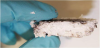
The PMMA-titania samples fabricated by Stewart et al. were freestanding disks with a thickness of 1 cm transverse to the flow of water through the porous wafer. Although these materials do exhibit high photocatalytic activity, nearly all of that activity is due to TiO2 very near to the sample surface. Figure 1 is a photograph of a PMMA- titania sample fabricated using the Stewart method which was then used to photocatalytically reduce Ag+ from a 0.1M aqueous AgNO3 solution containing methanol in 3-fold stoichiometric excess. The UV irradiance was provided from above the sample, and the Ag was photodeposited exclusively at the sample surface. Thick samples such as this contain substantial amounts of TiO2 within the sample core that is not photocatalytically active, but is still prone to loss from the composite during use as water flows through the porous membrane. Due to the poor mechanical integrity of thin porous PMMA films, samples thinner than 0.5 cm require deposition on a solid surface such as non-porous PMMA slab. In this work, 0.38 mm thick samples fabricated through the benchmark method [5] are compared to a revised fabrication method in which the titania is included within the PMMA-acetone-TWEEN solution, rather than in the coagulating water. The result is a material that has comparable photocatalytic activity while both using less TiO2 during fabrication and losing less TiO2 during long term usage.
Antibacterial TiO2-based photocatalytic extruded plastic films have been previous reported, which are similar to these PMMA-titania composites in that they have TiO2 mixed throughout the polymeric material. These extruded plastic films have shown evidence of increased activity after exposure to UV light [16]. This is due to an increase in the amount of exposed TiO2 on the surface of the material due to the photocatalytically oxidation of the support material by the TiO2 embedded within it. This preparatory UV exposure increased the exposed TiO2 after a 48 h preparative UV exposure. The photocatalytic activity of each sample was evaluated as the pseudo first order rate constant in the decolorization of 10 ppm methyl orange. The durability of these materials is evaluated by comparing the photocatalytic activity before and after a 1000 h period of continual UV exposure. The GPF is used as a metric for material comparison and the results are interpreted in view of the use of these materials in a long-term sustainable water purification application.
2. Materials and Method
2.1 Materials
Degussa/Evonik P-25 with an average surface area of 50 m2/g and an average particle size of 30 nm was the nanoscale TiO2 used. ACS grade acetone was purchased from Fisher Scientific along with TWEEN 80 surfactant. PMMA (molar mass of 75,000 g/mol) was purchased from Polysciences Inc. UV-transparent acrylic (PolycastSolacryl SUVT) with a thickness of 4.76 mm was used as the support material, and in order to control film thickness, a lab-built doctor’s blade was fabricated and calibrated with steel reference spacers. An ultraviolet light-emitting diode (UV-LED) lamp with λmax=365 nm was purchased from Xenopus Electronix (XeLED-Ni1UV-R4-365-E27-SS) and used for all degradation experiments. 13 W UV-compact fluorescent bulbs were used for the burn in and long-term UV exposure experiments.
2.2 Sample fabrication
All samples were fabricated and evaluated in triplicate. For the fabrication of the materials using the benchmark method, 1.8 g of PMMA was added to 10 mL of acetone followed by 0.21 g of TWEEN 80. This solution was applied over a 6.4 x 7.6 cm nonporous acrylic area and spread to a 0.38 mm thick coating using a lab-built doctor’s blade. The non-porous acrylic support slab surface was pre-roughened by the manufacturer, facilitating the adhesion of the porous PMMA-titania composite film. Immediately after the PMMA film was deposited, 10 mL of an aqueous dispersion of TiO2 was then sprayed over the solution with a hand-operated spray bottle. The coagulating solution concentration was varied, using the following concentrations: 1, 5, 10, and 15 %(w/v)TiO2. The resulting samples were dried overnight at 23⁰C and then washed by pouring 2 L of distilled water gently over the porous surface. The TiO2 content for each of the benchmark sample was determined by subtracting the average weight of samples that did not contain TiO2 from each sample that contained TiO2.
In order to make the revised samples, 10 mL of 15, 30, 44, or 56 %(w/w)TiO2/(PMMA) was mixed with 10 mL of acetone and 0.21 g of TWEEN 80. The resulting solution was applied to a 6.4 cm x 7.6 cm nonporous acrylic area and spread to a film thickness of 0.38 mm. 10 mL of distilled water was then sprayed over the solution. The resulting samples were dried overnight at 23⁰C and then washed by pouring 2 L of distilled water over the porous surface. The TiO2 content in each of the revised samples was determined from the difference of the weight of the acrylic slide before and after application, multiplied by the percent TiO2/PMMA used.
2.3 Photocatalytic testing
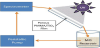
Photocatalytic testing was performed with each sample mounted at 34⁰ from horizontal. A UV LED lamp was placed 17.8 cm above the sample surface. The irradiance at the sample surface was 8 mW/ cm2, and was provided perpendicular to the sample surface. Using a peristaltic pump, 75 mL of 10 ppm methyl orange was continually recirculated across the sample surface as shown in Figure 2. The methyl orange flowed down the entire porous surface at a rate of 200 mL/min. The absorbance of the methyl orange at 463 nm was collected as a function of time over a period of 30 min. The pseudo first order rate constant determined from this data was used as the metric for photocatalytic activity of each sample.
2.4 Surface characterization and preparation
Scanning electron microscopy: SEM images of both a benchmark sample and a revised-method sample were captured using a variable pressure scanning electron microscope (Hitachi SU660).
Preliminary UV exposure: SP reliminary UV exposure: In order to maximize the amount of exposed TiO2 on the sample surface, each sample was exposed to UV light prior to testing. The preparative UV exposure involved horizontally submerging the sample in a distilled water bath with the TiO2 film facing upwards. A compact UV fluorescent bulb was centered 5.1 cm above each slide and 3.8 cm above the water surface, providing illumination at 2.5 mW/cm2. To determine the optimal UV exposure time, three benchmark samples containing 0.129 ± 0.093 g of TiO2, and three revised-method samples, containing 0.113 ± 0.020 g of TiO2 were exposed for 72 h. Every 12 h, the photocatalytic activity of each sample was determined. After each testing cycle, the samples were rotated to a different bulb within the reservoir to homogenize average UV exposure.
Methylene blue adsorption: The exposed TiO2 surface area of each sample type was evaluated using a methylene blue adsorbance test modified from Ratova et al. [16]. Each sample was completely submerged in approximately 520 mL of a stirred 100 ppm methylene blue/NaOH (pH 11) aqueous solution for 1 h. The NaOH (pH 11) causes the TiO2 surface to take on a negative charge, thus attracting the cationic methylene blue. The sample was then rinsed repeatedly with 150 mL of aqueous NaOH (pH 11). 4 or 5 rinses of 150 mL were needed to receive a colorless rinse solution. After rinsing, the slides were suspended in 520 mL of HCl (pH 3) for 1 h to remove the adsorbed methylene blue. The samples were then rinsed twice with 150 mL of HCl, and the combined HCl soak and wash solution was then diluted to 1 L prior to UV-Vis analysis at 665 nm. The amount of methylene blue adsorbed on each sample surface is a convenient estimation of the amount of exposed TiO2 on the sample surface [16].
2.5 Durability test
In order to evaluate the long term stability of these materials, samples were illuminated with a UV-CFL with a surface irradiance of 2.5 mW/cm2 for a total of 1000 h. Using three separate pumps, distilled water was recirculated from a common reservoir over the surface of separate triplicate samples. The slides were again placed at 34⁰ from horizontal with the water flowing over them at 210 mL/min. In total, six samples were tested, three benchmark samples containing 0.129 ± 0.093g of TiO2, and three revised-method samples containing 0.113 ± 0.020 g of TiO2. Following this 1000 h period, the TiO2 content of the water was quantified using ICP-MS (PerkinElmer Elan 9000).
3. Results and Discussion
3.1 Surface characterization and preparation
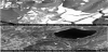
Scanning electron microscopy: The SEM images (Figure 3) clearly show a fundamental difference between the benchmark fabrication method and the revised technique. When the TiO2 is included within the coagulating water, the TiO2 is primarily deposited on the PMMA surface in relatively thick agglomerated rafts. Inclusion of the TiO2 within the PMMA matrix itself produces composites where the TiO2 is included throughout the PMMA matrix, both within the PMMA and on the PMMA surface. The embedded TiO2 is less prone to loss from the composite surface, but also benefits from the preliminary UV exposure process to maximize the amount of TiO2 exposed for the photocatalytic interaction with the contaminated water.
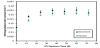
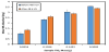
Preliminary UV exposure: Figure 4 displays the pseudo first order rate constant for the decolorization of methyl orange as a function of UV exposure time for the benchmark and revised method samples containing 0.129 ± 0.093 g and 0.113 ± 0.020 g of TiO2 respectively. The improvement in photocatalytic activity is apparently complete for both sample types after 36 h; and a 48 h UV exposure period was thus chosen for all subsequent samples.
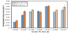
Methylene blue adsorption: The mass of methylene blue that adsorbs on the composite surface depends on the amount of TiO2 present in the sample and the effect of the UV exposure (Figure 5). The increase in photocatalytic activity that accompanies the preparatory UV exposure is attributed to an increase in exposed TiO2 on the sample surface as the TiO2 oxidizes the polymeric matrix in which it is embedded [16]. By comparing the mass of methylene blue adsorbed before and after 48 h UV exposure, (Figure 5), it is evident that UV exposure enhances TiO2 surface area for samples with low TiO2 content (up to 0.1 g). This surface area enhancement is not realized in samples with higher TiO2 content presumably because the exposed TiO2 present is already maximized, and ongoing UV exposure results in the loss of TiO2 from the composite surface.
3.2 Photocatalytic activity testing and TiO2 loss
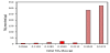
Samples of varying TiO2 content from both preparation methods were photocatalytically evaluated before and after the 48 h UV of these samples. The photocatalytic activity generally increases with pre-exposure. Figure 6 shows the pseudo first order rate constants for each the amount of TiO2 available, and there is not a substantial difference in activity between the benchmark and revised samples with similar amounts of photocatalyst present. In the process of measuring the pre and post UV-exposure photocatalytic activity, each sample was exposed to 2 h of UV illumination at an irradiance of 8 mW/cm2. The solutions used in this process were combined and analyzed for the presence of TiO2. The mass of titania lost from each sample is shown in Figure 7. There is a general and expected increase in TiO2 loss as the total TiO2 content of the sample is increased. The high TiO2 benchmark samples exhibit the most significant losses, as much of the TiO2 in these samples is present in aggregates on the sample surface as shown in the top panel in Figure 3. Since much of this TiO2 is not firmly embedded on or within the PMMA matrix, it is easily lost during use. The samples exhibiting the lowest TiO2 loss are the revised method-samples with the lowest TiO2 content.
3.3 Green photocatalysis factor
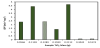
The GPF for each sample is shown in Figure 8. The samples with the highest GPF values are from the revised fabrication method, with the 0.113 ± 0.020 g revised sample yielding a GPF that is 83% greater than the benchmark sample containing 0.129 ± 0.093 g TiO2. The ideal amount of TiO2 is likely an application-dependent choice. If a composite material is intended for extended-term use, or in applications such as drinking water purification where nanoscale TiO2 tolerances are low, samples with minimal TiO2 content could be preferable despite the lower photocatalytic activity that they provide. The GPF provides a case-specific tool for comparing photocatalytic materials options across platforms.
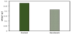
The lifetime of a photocatalytic material is of substantial interest for virtually any potential commercial or field application. To investigate the long-term durability of these materials, one triplicate set of benchmark (0.129 ± 0.093g TiO2) and one triplicate set of revised method samples (0.113 ± 0.020g TiO2) were exposed to UV light for 1000 h prior to re-testing of the photocatalytic activity of each sample and the quantification of the TiO2 loss during the 1000 h period. The degradation rate constant for the benchmark samples actually slightly increased by 2 %, and the revised-method samples decreased their activity by almost 16 %. In this 1000 h time period, the benchmark samples lost 0.116 mg TiO2, whereas the revised-method samples lost only 0.081 mg TiO2. The GPFs calculated from the post-1000 h activity and the corresponding TiO2 loss are shown in Figure 9. The GPF of the revised-method samples is 30 % larger than that of the benchmark method.
4. Conclusion
Incorporation of the TiO2 directly into the PMMA-acetone solution before coagulation with distilled water produces porous composite photocatalytic materials that use less TiO2 to achieve a comparable methyl orange degradation rate constant. When comparing samples of similar TiO2 content, the revised fabrication method reduces TiO2 use during sample preparation and makes it much easier to control the TiO2 content of the composite. TiO2 loss during photocatalytic use is also reduced with the revised fabrication process. The GPF provides a tool that incorporates both the amount of TiO2 lost during use and the photocatalytic activity when applying green chemistry concepts to photocatalytic systems. When comparing the GPF of samples with similar TiO2 content, the revised fabrication method is demonstrably improved over the benchmark method, providing a greener and better photocatalytic platform for photocatalytic water purification applications.
Competing Interests
The authors declare that they have no competing interests.
Acknowledgments
George Wetzel and Haijun Qian of Clemson University provided electron microscopy assistance. Sayed Hassan from the University of Georgia assisted with the Ti analysis for the assessment of the TiO2 lost from the composite surface. Degussa/Evonik graciously provided the TiO2 used in this study.