


1. Introduction
International conventions, which state laws and regulations to protect the environment, control the industrial revolution all over the world by demanding standards for the industrial outputs to be environmentally friendly. So the problem of coexistence of sustainable industry and safe environment are among challenges in the scene of fuel prices and availability.
Incineration is one of thermal treatment methods for waste materials in which the wastes are combusted at high temperatures although there are many other methods of remediation technologies; see for example [1]. Generally speaking, the methods can be classified into two categories: incineration and non-incineration.
1.1 Waste Incineration
Modern incinerators burn wastes in high – efficiency furnaces/ boilers to produce steam and/or electricity and incorporates modern air pollution control systems and continuous emissions monitor [2]. An incinerator is a furnace for burning refuse. Modern incinerators include pollution mitigation equipment such as flue-gas cleaning. Waste incineration has the following advantages:
- Volume reduction, especially for solids with a high combustible content
- Detoxification, especially for combustible carcinogens, pathologically contaminated material, toxic organic compounds, etc.
- Environmental impact mitigation, by destruction of all undesired secondary effluents or byproducts which create further significant pollution problems.
- Energy recovery, which is the most important advantage, especially when large quantities of waste are available, which is a good practice of waste to energy (WtE)
There are various types of incinerator plant design:
- Simple
- Fixed or moving grate combustion
- Rotary kiln
- Multiple stepped hearth
- Fluidized bed
Below is a brief description of the above mentioned incinerator:
1.1.1 Simple incinerator
The older and simpler kinds of incinerators were brick-lined cell with a metal grate over a lower ash pit, with one opening in the top or side for loading and another opening in the side of removing incombustible solids, called clinkers. Many small incinerators formerly found in apartment houses have now been replaced by waste compactors.
1.1.2 Fixed or moving grate combustion incinerator
These are large fixed hearth incinerators, with a moving grate. The moving grate enables the movement of waste through the combustion chamber to be optimized to allow a more efficient burn. These incinerators are typically used for combustion of municipal wastes [3].
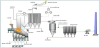
1.1.3 Rotary –kiln incinerator
Rotary-kiln incinerator is used by large municipalities and industrial plants. The design of incinerators has two chambers: a primary chamber and secondary chamber. The primary chamber in a rotary kiln incinerator consists of an inclined refractory lined cylindrical tube. Movement of the cylinder on its axis facilitates movement of waste. In the primary chamber, there is conversion of solid fractions to gases, through volatilization, destructive distillation and partial combustion reactions.
The secondary chamber is necessary to complete gas phase combustion reactions. The clinkers spill out at the end of the cylinder. A tall gas stack, fan, or steam jet supplies the needed draft. Ash drops through the grate, but many particles are carried along with the hot gases. The particles and any combustible gases may be combusted in an afterburner. To control air pollution, the combustion product gases are further treated with acid gas scrubbers to remove sulfuric acid and nitric acid emissions, and then routed through bag houses to remove particulates before the gases are released into the atmosphere [4].
1.1.4 Multiple stepped hearth incinerator
The waste is transported through the surface by moving teeth mounted on a central rotating shaft.
1.1.5 Fluidized bed incinerator
A strong airflow is forced through a sand bed where the air seeps through the sand until a point is reached where the sand particles separate to let the air through and mixing and churning occurs; thus, a fluidized bed is created and fuel and waste can now be introduced [5,6].
The sand with the pre-treated waste and/or fuel is kept suspended on pumped air currents and takes on a fluid like characteristic. The bed is thereby violently mixed and agitated keeping small inert particles and air in a fluid like state. This allows all of the mass of waste, fuel and sand to be fully circulated through the furnace.
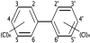
1.2 Polychlorinated biphenyls (PCBs)
Polychlorinated biphenyls (PCBs) are a class of organic compounds. PCBs classified as persistent organic pollutants. PCBs contain 1 to 10 chlorine atoms attached to biphenyl and a general chemical formula of C12H10-xClx (Figure 4 shows the structure of the PCBs), most PCBs were manufactured as:
- Cooling and insulating fluids for industrial transformers and capacitors.
- Stabilizing additives in flexible PVC coatings of electrical wiring and electronic components.
PCBs mixtures have been used for a variety of applications. These applications include dielectric fluids for capacitors and transformers, heat transfer fluids, hydraulic fluids, lubricating and cutting oils, and as additives in pesticides, paints, carbonless copy (NCR) paper, adhesives, sealants, plastics, reactive flame retardants, capacitors, insulating fluids in transformers, vacuum pump fluids, hydraulic fluids, and as a fixative for microscopy [7,8].
They were also used in surgical implants. However, PCBs production was banned in the 1970s due to the high toxicity of most PCBs congeners and mixtures. Research indicating they were likely carcinogens having the potential to adversely impact the environment and therefore undesirable as commercial products.
Most of the 209 different PCB solutions are colorless, odorless crystals. Commercial PCB mixtures are clear viscous liquids (the more highly chlorinated mixtures are more viscous), for example its viscosity may reach that of sticky resins. PCBs have low water solubility and low vapor pressures at room temperature, but they have high solubility in most organic solvents, oils and fats. Other physical and chemical properties vary widely across the class [9,10].
Examples of PCBs are PCB-resistant materials include viton, polyethylene, polyvinyl acetate (PVA), polytetraflouroethylene (PTFE), bytyl rubber, nitrile rubber, and neoprene.
1.3 Destruction methods of PCBs
PCBs are very stable compounds and are not easily degradable. They can be destroyed by chemical, thermal, and biochemical processes [11]. Though, it is extremely difficult to achieve full destruction. Also, the risk of creating extremely toxic dibenzodioxins and dibenzofurans is high through partial oxidation particularly due to high thermodynamic stability of PCBs.
All degradation mechanisms are difficult to sustain. Intentional degradation as a treatment of unwanted PCBs generally requires high heat or catalysis. Environmental and metabolic degradation generally proceeds quite slowly relative to many other compounds.
Microbial and chemical treatment of PCBs is possible; but in this work, incineration process will be discussed. Even PCBs do not ignite themselves; they can be combusted under extreme and carefully controlled conditions. The current regulations require that PCBs are burnt at a temperature of 1200°C for at least two seconds, in the presence of fuel oil and excess oxygen. A lack of oxygen can result in the formation of dioxins, or the incomplete destruction of the PCBs. Such specific conditions mean that it is extremely expensive to destroy on a tonnage scale, and it can only be used on PCB containing equipment and contaminated liquid. This method is not suitable for the decontamination of affected soils.
This work concentrate on modeling and simulating the incineration of hazardous including the emissions in both gas and solid phases and the combustion process and environmental issues. Here, we mainly study the kinetics and rates of species production from combustion process. Thus, the current work summarizes as follows:
- Theoretical mechanism for the incineration of hazardous substances (difficult to anticipate-wide variations in the constituents) PCBs include the number of chlorine atoms varies from (1 to 10). This model was developed to PCBs by Rovaglio et al. [12]. The results of the model were compared with experimental values reported by Rovaglio et al. [12].
- The physical properties of PCBs will be estimated if they were not available.
- The variation of temperature with time inside the incinerator will be evaluated.
- MATLAB code was developed to estimate the above mentioned items and explained in the second part of this paper.
2. Theoretical Approach
The general procedure for PCBs incineration is to burn mixtures containing PCBs like sand and other wastes. The structure consists of combustible fraction in which oils are the main component. In addition, some elements can be described as incombustible fractions and water content (moisture). Within the dry solid, it is necessary to distinguish between a combustible and burning fraction [13,14]. This gives rise to gas products. An inert fraction presenting what will be known also as the final solid ash component. A formal stoichiometry must be associated with the combustible fraction of the solid waste in order to account for the heterogeneous combustion.
2.1 Chemical equilibrium reaction of PCBs
Thus, the general stoichiometric relationship can be used to describe the structure of the feed stock to the incinerator [12].
CmHnOpSqNxCly + vO2O2→mCO2 +
However, the following general expression and chemical reaction for PCBs incineration is given by:
As in the case of the heterogeneous combustion, carbon mono-oxide (CO) is assumed to be the main oxidation product of carbon. The total combustion to CO2 takes place in the gas phase. Furthermore, waste compounds containing nitrogen are decomposed to give N2 and NO according to the following equation [12]:
N2 + O2→2NO
Which evaluates α (in equation 1) fraction of kiln temperature and excess oxygen.
The theoretical model [12] is used throughout this work and is solved using MATLAB. Mass and energy balances for both solid and gas phases are presented. The resulting equations is solved simultaneously to get the required temperatures, flow rates, energy produced, and gas phase concentrations. In addition, the amount of different persistent organic pollutants (POPs) in the input of waste incinerators is compared to that in the output [16].
2.1.1 Solid waste material balance
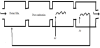
The solid waste is undergoing the heterogeneous combustion, passing through the rotary kiln incinerator, for a certain contact time θ (retention time), while the effect of the mechanical agitation induced by rotation consists of the renewal of the surface area exposed to hot gases containing oxygen. On this area, both volatilization and combustion processes take place. The bulk solid phase movement along the rotary kiln is not different in nature from that of similar units. The solid movement in the rotary kiln in the transit conditions is related to both gas and solid flows are assumed to be fast with respect to mass and energy dynamic balances. In agreement with the aforementioned assumptions the mass balance of the solid phase written as follows:
The evaluation of A, the interface area of the solid oxygen contact which is important sometimes to evaluate the rate of mass destruction, requires the knowledge of both gas and solid phase motions inside the rotary kiln. This area is function of kiln geometry and the operating conditions [15,16]. The maximum possible interface area depends also on particle diameter and solid angle of repose; if it is possible to estimate the average renewal surface velocity [Ar(m2/s)] then:
θ = 1.77.F.L.Φ0.5/S.D.N is the residence time for the solid material inside the rotary kiln [12]. The residence time varies depending on the parameters shown in the defining equation such as the square root of the dynamic angle of repose for the solid material inside the rotary kiln Φ, the type of the rotary kiln whether damped or not damped, F parameter which generally its value changes from 1or greater, internal diameter and length of the combustion chamber D and L respectively, kiln slope S, and the rotation speed N. Generally, the value of the retention time of the solids inside the rotary kiln is 15-60 minutes depending on the parameters above. Figure 5 shows the control volume where conservation equations are applied.
The destruction rate of Rdr can be derived based on the assumption of complete waste destruction:
In which, the destruction rate can be expressed as
,where the destruction rate can be related to the solid mass holdup inside the rotary kiln as follows:
2.1.2 Gas phase mass balance
Considering the possible auxiliary fuel (is represented by methane CH4) where the equation representing the rate of fuel reaction can be simply expressed as follows:
CH4 + 2O2→CO2 + 2H2O
Then the total gas phase material balance [12], which applies to the rotary kiln corresponds material balances for each component which can be described by:
Where i represent the following reaction species CO, CO2, H2O,
SO2, N2, HCL, NO, O2, with
Reaction 13 represents the overall waste destruction reaction producing CO2 as a result of heterogeneous combustion reaction. CO will be converted to CO2, should enough oxygen presents to accomplish reaction (2.13-d), or otherwise following reaction (2.13- e) when the oxygen amount is very small. Waste nitrogen is converted toN2 and NO.
The corresponding fractions are determined through a relationship which depends on kiln temperature and excess oxygen. The equilibrium conditions determined by reaction (13-c) refer to the afterburner system (homogeneous combustion) [17,18]. If auxiliary fuel is needed to maintain the required temperature, reactions (13-ab) and (13-b) allow total or partial methane combustion as a function of the oxygen presence to be taken into account.
Reactions from (13-a) and (13-b) besides (13-d) are very fast and can be considered under equilibrium conditions (complete conversion for CO and CO2) within the range of temperatures usually adopted (900°C to 1200°C). The extent of conversion for such reactions is in practice determined by the excess oxygen. Only reactions (13-c) and (13-e) have been considered in a kinetic regime [12], while the corresponding rate expressions have been deduced by generalizing some theoretical analysis. In particular, by considering the kiln, burner and post combustion chamber residence times separately, it is possible to evaluate the contributions to the production of NO corresponding to the different portions of the plant.
2.2 Energy Balance inside incinerator
The three modes of heat transfer, convection, condition, and radiation are present during the incineration process. Inside incinerators, the heat is generally transferred to the walls or to the upper surface of the solid beds by radiation and convection and to the lower (covered) surface by the regenerative action of the rotating kiln walls. The radiating gases in the kiln (not occupied by the wastefree volume) are also present within the boundaries of the burner and/or waste flames so that they may be considered as covering the entire free volume. Thus, due to the high gas temperature, solids and exposed walls receive heat primarily by radiation from the gas volume while both convective and regenerative heat flow play only a minor role in the overall heat transfer process. On the basis of the following assumptions [12]:
- Perfectly mixed conditions (outlet temperature of both the gas and solid is the same as that temperature inside the rotary kiln)
- Equilibrium condition between gas and solid phase (if present)
- Complete combustion (for both waste and auxiliary fuel)
Therefore, based on the above assumptions, the following energy balance around the control volume shown in figure 4 can be derived [12]:
Where
Equation (15) implies that waste and fuel are fed at the reference
temperature. It can be clearly seen that E is a strong function of
temperature. Equation (15) is used to express E as function of
temperature in the next section in details. The general radiation shape
factor (
The evaluation of the gas emissivity εG can be estimated graphically and/or experimentally referring to the suitable diagram concerned with radiating heat transfer, and as water and carbon dioxide are the main components in the gaseous product, the emission band that will be considered here is directly related to the combustion products: water and carbon dioxide. The emissivity of such components can be calculated through a polynomial regression of the experimental data as a function of the sum of the single partial pressures (PCW=PCO2+PH2O) and of the beam length (LW):
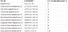
Here, x is x=log10 (PCW*LW) and the coefficients Cn , which are summarized in the research by Rovaglio et al. [12] when analyzing the effect of radiation energy, are given as follows.
This procedure will lead to an expression of emissivity as function of temperature that will be solved as independent variable with time in the dynamic modeling. The heat transfer by radiation cannot be neglected in deriving the model even this will lead to a source of high nonlinearity and so to a very stiff system, however, the radiation term consists of the following parameters:
, which is equivalent to the following:
Where:
The definition of the radiation energy requires the presence of the emissivity value which should be found in a form making it possible to be inserted in the model to account for the temperature variation. The total pressure inside the rotary kiln is given by:
PCW=PCO2+PH2O
which shows that all of the pressure produced comes from water vapor and carbon dioxide, the beam length LW can be found in the literature for different geometries, the next theoretical calculations is performed to derive the emissivity ε as function of temperature [12]:
where X=log10 (PCW*LW) and the coefficients Cn are summarized in table 2 where the final result is an expression of the form:
where θ is a theoretical constant.
An important feature of the radiation heat transfer is the shape factor. Equation 21 should be multiplied by the value of the shape factor. Referring to the literature figures is presented to account for the shape factor.
In the case of circular cylinder emitting to all its surfaces, the dimensions are important in the case of the rotary kiln which is used for PCBs incineration. The ratio between its length and radius is large and the ratio between outer and inner radius is zero (only one cylinder is used), the value of the shape factor for these conditions is 1.0.
The second major heat transfer mode is the convection heat transfer. The convective heat transfer coefficient is computed by a Dittus-Boelter relationship:
, where Nu is the Nusselt number and it can be calculated as hD/k, and so it can be corrected to take into account the effect of the entry length as follows [12]:
As for the transient heat condition within the furnace walls, the problem can be easily modeled by means of the classical equation of heat diffusion in one dimension to be solved for adjacent layers of different materials and with proper boundary conditions ensuring the continuity of heat fluxes. The real problem lies in choosing which discretization method is to be adopted and which numerical algorithm to use for integration purposes.
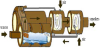
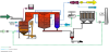
2.3 Energy balance in air heater
In the rotary kiln incineration plant configuration, there is a heat recovery section consisting of a sequence of heat exchangers placed after the burning system. These devices have a double function:
- Air combustion pre-heating to improve the thermal yield of the plant.
- Gas cooling to reduce water consumption inside the scrubbing section.
These apparatus consist of a metal shell which covers a cylinder of refractory and insulating material where, inside the enclosure, a coil of special alloy is placed. The cold air flows inside the coils while the hot gas moves along the refractory lined chamber.
Inside the heat exchangers, the hot gas temperature can be considered uniform, that is, a continuous stirred tank reactor (CSTR) scheme is assumed because of high turbulence due to the gas velocity and presence of coils and devices in the heaters [12]:
Here, Hin and Hout can be evaluated through equations (16 and 17) while Wf represents the hot gas flow rate which is assumed to be equal for inlet and outlet flows. The heat losses Qlosses through the walls can be determined as follows [12]:
The term inside the parenthesis defines the global heat transfer coefficient which takes into account both the convective and the radiative terms. In a similar manner, the heat exchanged between smokes and coils can be determined on the basis of the following relationship [12]:
Where the external convective coefficient he can be evaluated through the Nu number given by (John, 1997):
This refers to a system with cross-flow geometry.
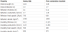
The model will be solved for the geometry and characteristics that are briefly summarized in table 3 which describes the pilot project designed [12] to investigate experimentally the incineration process. The model is based only on a limited number of variables measured and available from the plant as follows:
- Outlet gas temperature from the rotary kiln.
- Outlet gas temperature from the post combustion chamber.
- External skin temperature for the rotary kiln.
- External skin temperature for the post combustion chamber.
- Oxygen mole fraction in the post combustion gas outlet.
- Air temperature from heat exchangers.
However, the comparison is completed by the knowledge of the transient evolution of some input variables, such as: waste flow rate to the rotary kiln, Fuel flow rates to kiln and post combustion chamber, and air flow rate of the spiral heat exchanger [19,20].
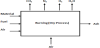
3. Mathematical Model and Computer Simulation
Mass and energy conservation laws produce a set of non-linear ordinary differential equations in which time is the independent variable and mass of ash, chemical species, and the total gas, and temperature are the dependent variables. It should be mentioned here that the conservation law of energy yields to the internal energy which depends on the temperature, and by some manipulations, the energy balance will be expressed in terms of temperature. The obtained sets of equations are solved using a MATLAB code developed for stiff differential equations through using ode23s solver. Details of the simulation algorithm and computer model to solve the set of nonlinear equations are given in the second part of this paper.
4. Model Validation
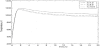
The most important parameter in the incineration process is the energy that can be utilized. Energy can be reflected by temperature results from the incineration. Figure 7 shows the temperature increase as a result from the incineration process.
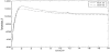
It can be clearly seen from figure 7 that as the number of chlorine atoms increases the temperature decreases. This is attributed to the fact that the heat of combustion of the feed waste is less when more chlorine atoms present.
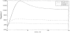
The effect of excess air on temperature distribution inside the rotary kiln can be seen in figure 8 which shows a drop in temperature for the increase in the excess air. This trend may be attributed to the presence of nitrogen element in the air fed which act as energy scavenger that removes the heat from the combustion chamber. Thus, the idea is to recover this heat and more from the exhaust gases.
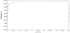
The same trend is noticed when the number of chlorine atoms exceeds 5. Figure 9 shows the general trend of decreasing temperature by increase in the number of chlorine atoms.
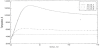
Figure 10 shows the increase in temperature as the number of chlorine atoms decreases. A decrease in hydrogen atoms as they are replaced by chlorine atoms affect negatively the amount of energy produced and reflected as a lower temperature, as more chlorine atoms present less temperature of the exhaust gas can be achieved.
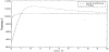
The results obtained will be compared with the published experimental data. As the modeling of the incineration of PCBs is based mainly on experimental studies and pilot plants, where the modeling and simulation procedure is still new and depends somehow on performing some experiments. Figure 11 shows a comparison for some of chlorinated wastes incinerated in rotary kilns.
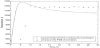
Figure 12a shows the temperature variation obtained from the combustion of pure methane. The steady-state value of the temperature is around 1050 K, and it corresponds to the combustion of methane in the presence of the waste. It can be shown that the temperature increase in the presence of PCBs is greater than that for pure methane (figure 12b). This is attributed to the fact that PCBs have some internal energy stored and released by incineration which can be used as energy source. However, the trend in the temperature variation is little bit different due to the fact that combustion mechanism is different in the presence of different reactions and reactant components.
For pure methane combustion, the present temperature variations with oxygen mole fraction are compared with experimental results on figure 13.
Figure 13 shows the same trend can be obtained by the model developed in this study with the experimental work of Baukal [1]. It should be mentioned here that the oxygen concentration will decrease as time proceed and its concentration can be kept high by adjusting the excess air. Once the real procedure and exact concentrations of methane gas and oxygen flow rates are known, a curve fit can be used to create correlations. This requires further experimental research to produce an extended data bank of temperature versus the oxygen concentration.
Certain types of pollutants are expected in almost all types and conditions of incineration such as furan and dioxin. One of the advantages of the present incineration model is that traces of such pollutants exist. The assumed plant for incineration that includes a cooling tower will guarantee that neither furan nor dioxin is formed. That is the cooling to 150 °C which is used as design criterion for the heat recovery units.
5. Conclusion
A generalized model for the dynamic simulation of PCBs incineration in rotary kilns was developed. In addition to assumed chemical reaction, mass and energy balances are written to derive the mathematical model. This model is able to verify the variations in operating conditions, chemical structure of the material being incinerated, and waste-feeding operations.
The analysis of the results obtained from the model proves that the model is able to produce comparable results with software designed for rotary kiln incinerators and with the experimental results. Empirical correlations for a certain type of wastes can be derived if more experimental data become available.
For PCBs a temperature of 1200K is reached. The value of temperature varies depending on the number of chlorine atoms and amount of excess air. As the number of chlorine atoms and amount of excess air increases the temperature decreases. The major incineration products are carbon dioxide, water vapor, and hydrochloric acid. Their concentration in the outlet gas stream depends on the temperature, chlorine atoms in PCBs, and amount of excess air.
Competing Interests
The authors have declared that no competing interests exist.
Author Contributions
All the authors substantially contributed to the study conception and design as well as the acquisition and interpretation of the data and drafting the manuscript.
Nomenclature
A → Area, m2
C → Species hold up, Kg
Cp → Specific heat at constant pressure, J/kg K
Cv → Specific heat at constant volume, J/kg k
D → Internal combustion chamber diameter, m
Erad → Radiation Energy, W
F → Factor: 1 for undammed kilns; greater than 1 for dammed kilns
h → Convective heat transfer coefficient, W/ m2k
H → Enthalpy J/Kg
k → Thermal conductivity, W/mk
l → Free mean path of a photon inside the combustion chamber, m
L → Internal combustion chamber length, m
M → Holdup inside the kiln, Kg
N → Rotational speed of kils, rps
Nu → Nusselt number
P → Pressure in the gas,atm
PM → Molecular weight, Kg/Kmol
Pr → Prandtl number
Q → Heat,W
R → Reaction rate, Kg/s
Re → Reynolds number
S → Kiln slope (degree from horizontal)
T → Temperature, K
E → energy, J
v → Velocity, m/s
V → Combustion chamber volume, m3
W → Flow rate, Kg/s
y → Mole fraction
Superscripts
Bulk → Bulk phase
g → Gas phase
in → Inlet property
out → Outlet property
s → Solid phase
Subscripts
Air → Air phase
bf → Burning fraction
CH4 → Methane
CW → Carbon dioxide and water vapor phase
dr → Destruction rate
f → Flue gas
gas → Gas phase
h → Hot fluid
H2O → Water and water vapor
i → Stream components
ki → Kiln property
Ln,n → Log mean property
N2 → Nitrogen
O2 → Oxygen
r → Renewal property
ref → Reference state
solid → Solid phase
tot → Total property
w → Wall
Waste → Waste
Greek symbols
β → Volume expansivity
Υ → Geometry coefficient
Δ → Different operator
ε → Emissivity
η → Boiler efficiency
μ → Stoichiometric coefficient for waste combustion, KmolO2/kmol waste refers to the combustible fraction and the O2 consumption refers to CO2 formation
ρ → Density, Kg/m3
σ → Stefan Boltzmann constant, W/m2k4
τ → Gas transmittance
Φ → Dynamic angle of response for the solid material inside the rotary kiln
Ω → Fraction