


1. Introduction
Thermoelectric eects are exploited for the operation of solid state devices known as thermoelectric modules (TEM), which are used in diverse applications [1]. For example in modern laser, optical and radioelectronic systems cannot be built without thermoelectric cooling and thermostatically controlled systems, also are needed for precision temperature control of photonics [4] components: Electronic components (memory, ASICs,) meet performance and reliability specs over wide range of operating temperatures; e.g., Intel Atom (bare die) microprocessor requires 0-85°C case (die) temperature [5].
A thermoelectric module is a device, which produce a temperature difference with current flow by means of an eect known as Peltier eect, due to this eect the TE has a similar function to that of a refrigerator. Conversely, if the device is submitted to a temperature difference, a potential difference is created which can be used to power an external load, this effect is known as Seebeck effect.
A thermoelectric device have the following advantages: no moving parts, ideal when precise temperature control is required, ability to lower temperature below ambient, heat transport controlled by current input, compact size make them useful for applications where size or weight is a constraint, ability to alternate between heating and cooling. No working fluids and gases pollutants, low noise operation [2].
The TEM's are made of thermoelectrics material, whose quality of performance is given by a parameter known as the gure of merit. It is dened by the following equation, [6]:
where ρ is the electrical resistivity, k is the thermal conductivity, and α is the Seebeck Coefficient, these properties are dependent on temperature. The most basic model of a TEM is a thermocouple (a P leg matched to N leg), for which the figure of merit is given by the equation (2).
Then a primary goal in thermoelectricity, is to get devices whose gure of merit is greater than the standard value of 1. For example , even for state of art Bi2Te3 which has a zT of 1.1, the eective device ZT is only about 0:7 based on the overall performance of the device as a cooler or power generator [9].
A technique for improving the design of TEM's is to work with the equations of the theory of thermoelectricity and heat balances applied to heat exchangers, taking into account geometric or dimensional parameters of the thermoelectric module. For example transfer areas of heat sinks, thermoelement length, the number of thermocouples, the geometric ratio of the cross-sectional area.
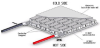
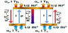
The basic thermoelectric device is a thermocouple, which consists of a p-type and n-type semiconductor elements, or legs. Copper commutation tabs are used to interconnect legs. Thermoelectric module are made of multiple thermocouples connected electrically in series and sandwiched between two ceramic plates. The number of thermocouples may vary greatly from several elements to hundred of units. This allows to construct a TEC of a desirable cooling capacity ranging from fractions of Watts to hundreds of Watts.
For the improvement of thermoelectric devices, the following aspects should be addressed
- Areas of each type legs need to be optimized
- Two types of legs should have comparable properties
- Current input to the device needs to be optimized
- Have the capability of operating in new and broader temperature regimes,
2. Equation Figure of Merit
This section presents the basic theory of the figure of merit for a thermocouple. The quantity of greatest importance for a refrigerator is the coefficient of performance (COP), which is defined as the ratio of heat extracted from the source to the expenditure of electrical energy [3].
The expression for the cooling power is
where
The rate of expenditure of electrical energy is:
The COP ϕ, is then given by
The current Iϕ, that yields the maximum coefficient of performance is given by
At this current, the COP is given by:
where,
this quantity is known as the gure of merit of the thermocouple and may be optimised for a given pair of thermoelectric materials. The aim should be to make the product (kp+kn)(Rp+Rn) as small as possible. This result is obtained when the form factors for the two legs satisfy the relation:
when (11) is satised, ZT is given by:
This gure of merit is usually applied to a pair of materials, is say a thermocouple.
3. Maximum Temperature Difference: Comparison Between A Unileg and Thermocouple
One of the most important characteristics of a thermocouple for cooling applications is the maximum temperature difference that can be reached through the Peltier effect. This quantity, ΔTmax, can be calculated, when the COP is equal zero. So that:
In this section we make a comparison between the maximum temperature difference of a unileg (which is a useful resource in the design of thermoelectric systems) and the maximum temperature difference of a thermocouple (two legs of the same material), using the relationship of the thermoelectric properties ρ and k and the geometric parameters, in particular the area ratio. This step is important in the experimental practice.
The equation of the maximum temperature difference for a thermocouple, with the two legs of the same length but dierent area is:
where:
is the area ratio.
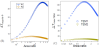
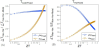
The figure (3.B and 3.C) show two cases to the equation (14), the maximum temperature difference of one thermoelectric leg plus metal wire (unileg) and the maximum temperature difference of two thermoelectric legs of same material (thermocouple), respectively, both as function of area ratio. We have used two dierent thermoelectric materials (a conventional and the other is a novel material) to show the useful of the equation (14).
Now when the thermocouple is made of two legs of the same material, both of the same area and same length (conventional model), the maximum temperature difference is given by the equation (16).
For the design of a thermocouple (which is the real element that
compose to the TEM) for cooling, the
the equation (17) show the relationship between the thermoelectric properties (α, ρ, k) and geometric parameters, in this case the transversal section areas of legs. The figure (4) shows the maximum temperature difference ratio as function of area ratio,
A useful technique for the purposes of measuring thermoelectric properties is to maintain the set temperature in any of the two points (cold or hot), furthermore the study of this aspect could be useful for developing an application where one of the temperatures (Tcold or Thot) remain fixed, the figure (5.A) and figure (5.B) show the maximum temperature difference ratio as function of ZT at Tcold fixed and at Thot fixed respectively
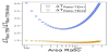
To have an approximate value of the maximum temperature difference that could be achieved with a thermocouple with reference to the maximum temperature difference achieved by a unileg, we have maximized the equation (17) with respect to γ,
It is noteworthy that the equation (18) shows very clearly the relationship between the thermoelectric properties and geometrical parameters of the legs, in this case (ρ, k) whit (AN, AP).
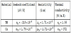
To show the usefulness of the equation (19), it is evaluated by using the numerical values for the properties of a thermoelectric material (TM) figure (6), while the metal in this case is copper (Cu).
The result is:
this value indicates that the maximum value of the temperature
difference reached by a thermocouple
4. Conclusion
In this work we have studied a basic aspect for the design of
a conventional thermocouple for thermoelectric cooling, with
reference to the model of a unileg. We have show how to approach
the maximum temperature difference of a thermocouple (two legs of
the same material) by mean of the maximum temperature difference
of a unileg, by definition of the maximum temperature ratio
Competing Interests
The authors declare that they have no competing interests.
Acknowledgments
We thank to CONACYT for supporting the academic stay at CALTECH.