


1. Introduction
Bulk metallic glasses (BMGs) exhibit a series of excellent mechanical properties at ambient temperature, such as high strength, large elastic limit, and superior corrosion and wear resistance [1], which render them the potential as structural materials. However, almost all BMGs suffer from a fatal problem that they exhibit catastrophic failure without obvious macroscopic plasticity upon loading at room temperature, due to the prompt propagation of highly localized shear bands [2]. In order to dispose of the problem, a variety of methods have been applied recently. One effective method is to introduce a second phase with ductility into the glass matrix to fabricate metallic glass matrix composites (MGMCs) [3-8]. The second phase works as an obstacle to prevent the prompt propagation of shear bands and facilitate their multiplication, avoiding an early failure of the composites upon loading. Consequently, improved plasticity is available for MGMCs. Up to now, there are mainly three ways to produce MGMCs: precipitation of a dendritic crystalline phase from the glass matrix (in-situ composites) [3-6]; casting of a glass-forming alloy and reinforcements such as crystalline particles and fibers (exsitu composites) [7,8]; and production of a nanocrystalline phase in metallic glass [9,10]. Among these composites, the most common are the in-situ composites developed by copper-mold-suction casting due to the convenient and easy fabrication.
The in-situ MGMCs usually exhibit macroscopic plasticity upon quasi-static loading at room temperature due to the interaction between the dendrites and the multiple shear bands [3-6]. However, when they are subjected to high strain-rate loading, the situation may be different. The information on the mechanical properties of the materials upon dynamic loading is of great importance, which can be effectively applied to strategic fields, such as defense, aerospace, and precision machinery [11,12]. In spite of the several investigations conducted on the dynamic compression behavior of in-situ MGMCs [11-16], agreements have been rarely reached on the deformation mechanisms. Qiao et al. [11] have found that in-situ Zr-based MGMCs exhibited ultrahigh strength and considerable plasticity upon quasi-static compressive loading, but failed abruptly with brittleness upon dynamic compression due to the absence of multiple shear bands. Similar results of a Zr-based MGMC were also reported by Chen et al. [13]. However, Jeon et al. [12] have reported that the maximum fracture strain of Zr-based MGMCs upon dynamic loading amounts to as high as 10%. Recently, Wang et al. [14] have found that the total strain of an in-situ Ti-based MGMC upon dynamic loading is over 7%. Similarly, a Ti-based MGMC, exhibiting distinguished work-hardening capability upon dynamic compressive loading, was investigated, and the fracture strain was up to 10.6% [15]. Additionally, considerable plasticity was available, when in-situ Tibased dendrite/metallic glass matrix composites were subjected to the dynamic compression [16]. The inconsonant results motivate more investigations on the dynamic compression behavior of in-situ MGMCs, which can help to get a better understanding of deformation and fracture mechanisms.short milling time.
Ti alloys are widely used in aerospace field owing to their unique combination of physical and mechanical properties, such as low density and high specific stiffness and strength [17]. Based on this, a new kind of in-situ Ti-based metallic glass matrix composite is fabricated by copper-mold-suction casting in this study. Quasi-static and dynamic compression experiments are conducted to explore the deformation and fracture mechanisms of the present in-situ MGMC. Dependence of the mechanical properties on microstructures and loading rates is investigated.
2. Experimental
An ingot of a nominal composition: Ti46Zr20V12Cu5Be17 (at. %) was prepared by arc-melting a mixture of Ti, Zr, V, Cu, and Be with purity higher than 99.9% under a Ti-gettered argon atmosphere. In order to ensure homogeneity, the master alloy ingot was re-melted at least four times. Then, the rod-like samples with 3 mm in diameter and 85 mm in length were fabricated by suctioning the molten ingot into a copper mold. The cross sections of the rods were polished, and etched by a solution of 40 mL HF, 20 mL HNO3, 40 mL HCl, and 200 mL H2O.
The scanning-electron microscopy (SEM) was employed to investigate
the microstructure. The phases of the samples were analyzed by the
X-ray diffraction (XRD). Uniaxial quasi-static compressions were
performed on cylindrical samples with 3 mm in length under a strain
rate of 5 × 10⁻⁴ s-1 at room temperature. The dynamic compressive
loadings were conducted at ambient temperature on samples with
an aspect ratio of 1:1 using a split Hopkinson pressure bar (SHPB)
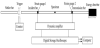
apparatus. An SHPB apparatus was illustrated in Figure 1 [11], which
consisted of input and output bars, which were made of high strength
steels. The sample was located between the input and output bars.
The striker bar was launched from a gas gun towards the input bar.
A compressive stress pulse was generated, when the input bar was
impacted by the striker bar, which would travel along the input bar
towards the sample and subject it to the required stress levels. A
portion of the pulse was reflected back into the input bar, while the
remaining pulse was transmitted into the output bar. The input and
output bars were both mounted with strain gages at midway points
along the length of the bars to capture the strain signals associated
with the waves when they passed by. Therefore, both the compressive
strain rate,
Where A, L, E, and C were the cross section area, length, elastic modulus, and elastic wave velocity, respectively. The s and b represented the sample and pressure bar, respectively. Therefore, the stress-strain curves upon dynamic compression could be obtained by eliminating the time parameter, t. More descriptions of the dynamic compression process could be found elsewhere [11, 18]. After the quasi-static and dynamic compressions, lateral surfaces and fracture surfaces of the deformed samples were investigated by SEM to identify the deformation and fracture mechanisms.
3. Results and Discussion
Figure 2 shows the typical SEM image of the microstructure of the in-situ composite. It can be seen that dendrites are homogeneously distributed within the featureless and continuous glass matrix. The volume fraction of the dendrites is approximately 60%, and the average diameter of dendritic arms is about 0.5 μm. During cooling of the melt from high temperature, the embedding dendrites are formed by nucleation and dendritic growth of the bcc β-Ti phase, followed by the solidification of the remaining liquid alloy. The XRD pattern of the composite, shown in the inset, indicates that only the β-Ti crystalline phase with a body-centered-cubic (bcc) structure can be detected. The sharp diffraction peaks of the β-Ti phase are superimposed on the broad diffuse scattering amorphous maxima, which is in agreement with the SEM result, further identifying the dual-phase structure.
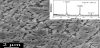
Figure 3(a) displays the quasi-static compressive engineering stress-strain curve of the composite. It can be seen that the yielding strength is about 1,600 MPa. After yielding, a work-hardening behavior prevails until the final fracture takes place, accompanied by the ultimate strength of 1,980 MPa and the fracture strain of about 8.8 %. Analogical phenomena are found previously in in-situ Ti-based MGMCs [14-16]. There are several empirical formulas to explain the work-hardening capacity of metallic materials, among which, the Hollomon equation [19] is widely used, since it goes well with the uniform plastic deformation stage in the true stress-strain curve of metallic materials. The equation is expressed as follows:
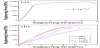
Where S is the true stress, K is the strengthening coefficient, ε is the true strain, and n, indicating the ability of resistance to continuous plastic deformation, is the work-hardening exponent. The workhardening exponent, n, of the present composite, calculated based on the Hollomon equation, is about 0.15, which is several times larger than that of Ti-6Al-4V alloys (0.03~0.06), extensively applied in the field of aerospace [20]. Generally, the work-hardening exponent, n, is inversely proportion to the yielding strength, σy, which can be identified by the comparison between the present results and the previous studies by Qiao et al. [21] (n = 0.25, σy = 1,300 MPa). For the composite upon quasi-static loading, the inconsistent deformation exists for the dendrites and glass matrix, due to the mismatch of Young’s modulus and yielding strengths between the two phases [3,22,23]. Initially, the applied stress is relatively low, so both of the crystalline dendrites and the glass matrix deform elastically, the composite, therefore, goes through the elastic stage. When the stress increases continually, a critical point will be approached, where the dendrites begin to yield, and work-hardening appears simultaneously.
However, owing to possessing higher strength than the dendrites, the glass matrix is still at the stage of the elastic deformation. Meanwhile, primary shear bands would initially nucleate near the interface of the two phases, which propagate along the favorable direction. When the propagation is hindered by the crystalline dendrites, the shear bands either are arrested by the crystalline phases or bypass the barriers wriggly [1,3,21]. Consequently, the multiplication of shear bands prevails within the glass matrix, and plasticity of the composite is greatly improved. Therefore, the work hardening of the crystalline dendrites is responsible for the macroscopic plasticity of the composite, high strength of the glass matrix accounts for the large yielding and ultimate strengths of the composite. When the crystalline dendrites can not undertake more plastic deformation, further deformation of the composite would be dominated by the glass matrix. Unfortunately, the monolithic amorphous alloys exhibit strain-softening rather than work-hardening after yielding [24]. As a result, the final fracture takes place along the maximum shear stress direction.
Figure 3(b) exhibits the engineering stress-strain curves of the composites upon dynamic compressive loading with different strain rates. Unlike the quasi-static case, the samples begin to lose their load-carrying capacity, once the maximum stress is approached, i.e., all of them have a fracture without obvious macroscopic plasticity. The ultimate strength of the samples ranges from 1,710 MPa to 2,030 MPa. Zener and Hollomon [25] proposed a constitutive equation for the coupled strain rate / temperature dependence of irons and steels as follows:
Where σ0 and (dε/dt)0 are reference flow stress and strain rate, respectively, Q represents the activation energy, R indicates the gas constant, T refers to the temperature, and r is an experimental constant. It can be seen that σ increases with the larger strain rate, dε/dt, at a given temperature. Additionally, the crystalline alloys, for example, Ti-6Al-4V alloys , usually exhibit increased yielding and ultimate strengths upon dynamic loading compared to quasi-static loading [18]. However, a weak dependence of the strength on the strain rate is generally obtained for monolithic BMGs and in-situ MGMCs [11, 26]. The phenomena can be explained by that the above analysis of the dependence of the deformation of the crystalline alloys on the strain rate is based on the dislocation mechanism, whereas the dislocations are absent in BMGs. And due to the presence of the two phases, the situation becomes more complicated for the in-situ MGMCs upon dynamic compression.
For the present composites upon dynamic loading, there is not sufficient time for the generation of multiple shear bands. Once initiated, the shear bands would propagate rapidly, leading to the decrease of the resistance to fracture. Therefore, all the composites fail with brittleness. Spaepen [27] has concluded the softening mechanism during inhomogeneous deformation for BMGs: if there is a lowering of viscosity in the shear bands, there must be an increase of the free volumes.
where
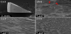
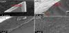
In order to better understand the deformation mechanisms of the current composite, it is necessary to investigate the fractographs of the composites. Figure 4(a) shows the lateral surface of the sample fractured upon quasi-static compression. The fracture plane inclines about 45º with respect to the compressive loading direction. Usually, the shearing angle of metallic glasses is less than 45º [28-30]. However, in terms of in-situ MGMCs, when subjected to applied stress, the fracture would proceed along the maximum shear stress direction (about 450 with the loading direction) due to the presence of crystalline dendrites. Figure 4(b) displays the magnified image for the lateral surface of the deformed sample. Profuse shear bands are distributed on the lateral surface near the fracture plane, indicating macroscopic plasticity of the sample. It can be seen that the shear bands are mainly in two different directions, which are basically perpendicular to each other. Several microcracks, indicated by the red arrows, can be also observed, which are formed along the shear bands due to severe plastic deformation. Figure 4(c) shows dense shear bands parallel to each other with an average spacing of 0.8 μm. Figure 4(d) presents the typical fracture surface of the composite. Few vein patterns can be found, and abundant resolidified liquid droplets, associated with the adiabatic heating [28], prevail on the whole facture surface. Figure 5(a) illustrates the lateral surface of the deformed sample, subjected to the dynamic compression. A piece of the fragment has broken away from the whole specimen, as indicated by the red ellipse, partly demonstrating that the specimen fracture with brittleness. Figure 5(b) presents the magnified image for the lateral surface of the deformed sample. There are no traces of multiple shear bands, and only primary shear bands along the fracture plane can be found. As the quasi-static case, microcrack, indicated by the red arrow, comes into being along the primary shear band. The area, marked by the red rectangular in Figure 5(b), is magnified and displayed in Figure 5(c), showing the details of the shear bands. Figure 5(d) shows the fracture surface of the sample. Compared with that upon quasi-static compression, the dynamic fracture surface is much smoother. According to the investigation by Chen et al. [13], the increased strain rate leading to the decrease in the shear band toughness, Kc, which measures the critical energy dissipated in the shear bands. Upon quasi-static loading, the larger shear band toughness, Kc, denotes higher energy dissipation in the shear bands, resulting in the higher temperature rise for the specimen in the instant of fracture. Therefore, more resolidified droplets can be observed on the fracture surface of the sample upon quasi-static compression.
4. Conclusion
An in-situ Ti-based metallic glass matrix composite with the composition of Ti46Zr20V12Cu5Be17 (at. %), containing homogeneously distributed β-Ti dendrites within the glass matrix, was fabricated by copper-mold-suction casting. Upon quasi-static compression, macroscopic plasticity was available for the composite, characterized by multiple shear bands on the lateral surface and abundant droplets on the fracture surface in the micro. However, when subjected to the dynamic loading, all the samples fractured with brittleness, due to the insufficient time for multiple shear bands to be generated. The fractographs of the composites upon quasi-static and dynamic compressions were observed and compared.
Competing Interests
The author declare that he has no competing interests exits.
Author Contributions
All the authors substantially contributed to the study conception and design as well as the acquisition and interpretation of the data and drafting the manuscript.
Acknowledgments
J.W.Q. would like to acknowledge the financial support of National
Natural Science Foundation of China (No. 51371122), the Program
for the Innovative Talents of Higher Learning Institutions of Shanxi
(2013), and the project of State Key Laboratory of Explosion Science
and Technology (Beijing Institute of Technology), and the project
number is KFJJ16-07M.
H.J.Y. would like to acknowledge the financial
support from the National Natural Science Foundation of China (No.
51401141), State Key Lab of Advanced Metals and Materials (No.
2013-Z03), and the Youth Science Foundation of Shanxi Province,
China (No. 2014021017-3).
Z.H.W. would like to acknowledge the
National Natural Science Foundation of China (No. 11390362).