


1. Introduction
Inspiration on the increasing applications of magneto rheological fluid leads the researchers to design and develop the novel sensors applicable in the field of electrical, electronic and biomedical engineering. The interesting behavior of MR fluid is the change in apparent viscosity with respect to the change in magnetic field. Some of the innovative products using MR fluids include dampers, clutches, brakes, hydraulic valves and actuators [1-6] and many of these products are already commercialized [7]. Normally, the devices that use MR fluids are classified into two types based on particle shape: i) sphere iron particle and ii) plate iron particle [8,9]. The main aim of this review paper is to provide the reader with a basic understanding of the design techniques of various sensors using MR fluid. Therefore, we have reviewed the available four different MR fluid based sensors implemented in the real time. The sensors discussed in this paper are the following: 1) resonant sensor, 2) current sensor, 3) magnetic flux sensor, and 4) tactile sensor.
In the past few years, resonant sensing has become a very popular method for measuring physical and chemical phenomena because of its high sensitivity, stability, good accuracy and resolution [10]. In addition, quasi digital nature of the frequency signal eases interfacing to readout and processing circuitry and improves noise immunity [11]. The squeeze mode yield stress measurement system is designed using this resonant sensor concept [12]. In this measurement system, the piezolaminated cantilever beam is coupled with electromagnetic coil based MR fluid squeezing setup. The cantilever beam is maintained at resonance using simple closed loop electronics. The magnetic field produced by the coil changes the viscosity of MR fluids and produces an additional stiffness to the resonating cantilever beam. The shift in resonant frequency due to the change in viscosity of the MR fluid is measured and the shift in frequency is analytically related to the yield stress. Using the same resonant concept, an attempt is made to design current sensor using magneto rheological fluids [13] as the information regarding current flow is very much required in electrical and electronics applications [14]. The current induced magnetic field produced by the coil changes the viscosity of MR fluids and produces an additional stiffness to the resonating cantilever beam. The shift in resonant frequency due to the change in viscosity of the MR fluid is measured and the shift in frequency is related to the input electrical current to the coil.
Another interesting sensor designed using magneto rheological fluid is magnetic flux sensor. Magnetic flux sensors finds wide range of applications in magnetic anomaly detection technology, position tracking of human body movement, magnetic resonance imaging technology for medical / biological applications, detection of machined cracks and mechanical torque measurement [15-20]. Generally, there are two types of magnetic sensors, namely vector and scalar magnetometers based on the method used to measure the magnetic field. Vector magnetometers include search coil, fluxgate, superconductor, magneto resistive, spin valve, giant magneto impedance, magneto strictive, magneto optical and MEMS based magnetometers, whereas scalar magnetometers include optically pumped, nuclear precession and over hauser magnetometers [21,22]. An effort has been made to design magnetic flux sensor using a magneto rheological fluid in [23]. The change in the magnetic field varies the electrical resistive characteristics of the MR fluid. Utilizing this salient mechanism, an MRF variable resistor system is devised to measure the change in the magnetic flux. The designed sensor finds application in many electrical control systems. In addition to these sensors, tactile display is designed and implemented using MR fluid for biomedical application in [24]. The tactile sensors reported in the literature uses the materials such as piezoelectric actuators [25], shape memory alloy (SMA) wires [26-30], pneumatics [31-33], solenoids [34,35], and electrostatics [36]. A tactile mechanism similar to organs is devised by utilizing MR fluids based on force responses of biological substance. This tactile sensor finds application in robotic system in minimally invasive surgery.
This paper is organized as follows. The section 2 describes the characteristics of the MR fluid, section 3 describes the different sensor design and the conclusion is drawn in section 4.
2. Characteristics of MR fluid
The invention of magneto rheological fluid started with the design
of clutch by Rabinow in the year 1948 [2]. The MR fluid is one of the
classical intelligent materials which change its rheological behavior
dramatically with the application of magnetic field. Basically the MR
fluid is the free flowing liquid with the absence of the magnetic field
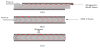
as shown in Figure 1a. The viscosity of the MR fluid increases twice
in magnitude and becomes a solid with the short response time (few
milliseconds) when the fluid is placed under the strong magnetic field
as shown in Figure 1b. The strength of MR fluid is expressed by its
operation mode and its corresponding mode dependent yield stress.
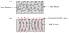
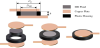
Normally, the operational mode of MR fluid is classified into three
types: i) shear mode, ii) flow mode and iii) squeeze mode as shown
in Figure 2a, Figure 2b and Figure 2c respectively. In all three modes,
the MR fluid is located between two plates with different operational
circumstances. In the shear mode, the MR fluid is located between
two plates and sheared parallel to the plate that slides or rotates
relative to the other plate. In the flow mode, the pressurized MR fluid
is made to flow between two fixed plates and the flow resistance can
be controlled by the magnetic field. In the squeeze mode, the MR
fluid is placed between movable parallel plates with the perpendicular
magnetic field to the plate surface. As the parallel plate moves close to
each other it squeezes the MR fluid. One of the most important and
potentially applicable modes for designing MR product is shear mode
operation. The basic properties and behaviour of MR fluid in shear
mode actuation and damping are completely studied and reported
[37-40]. The most powerful mode of operation of MR fluid is squeeze
mode but relatively not much literature is reported [41,42]. The
behavior of MR fluid is commonly represented as a Bingham – Plastic
model having a variable yield stress
Where
3. Sensor Design using MR Fluid
The design of different types of dampers and clutches using magneto rheological fluid is the main concern of researchers in the last few decades. Due to the advancement in the MR fluid technology, the researchers are motivated to design the novel sensors using MR fluid such as resonant sensor, current sensor, variable resistor and tactile sensor.
3.1 Resonant sensor
In the past few years, resonant sensing has become a very popular method for measuring physical and chemical phenomena. A resonant sensor is a device with an element vibrating at resonance, which changes its output frequency as a function of a physical parameter (i.e. viscosity of MR fluid). Using this resonance concept, a new measurement method for the field- dependent yield stress of MR fluid subjected to squeeze mode operation is designed and implemented in [12]. The proposed method is accomplished by utilizing resonant behavior of the cantilever structure associated with piezoelectric excitation and detection. The sensor output is digital in the sense that it is basically independent of analog levels and can be connected directly to digital circuitry. Advantages of the resonant sensor are its high stability, high resolution and quasi digital output.
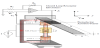
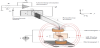
The devised measurement system consists of a flexible aluminum beam with the collocated piezoelectric patches bonded at a distance of r1 from the fixed. The piezo on the upper surface acts as an actuator and one on the lower surface acts as a sensor. As shown in Figure 3, the two bobbin type electromagnetic coils with C and I shaped core are placed face to face in z-axis to form a closed magnetic field path. The I shaped core is used for electromagnetic coil 1, which attached to the vibrating cantilever beam at a distance of r0 from the fixed end and the C shaped core is used for coil 2, which is mounted on the base. Both the cores are operated as a separate entity with gap of ‘g’ and ‘d’ respectively between the two ends of the cores. A cylindrical container having magnetorheological fluid is placed in the gap ‘d’ and the I shaped iron core of coil 1 is half immersed to form a squeeze mode MR operation and the small air gap ‘g’ is formed between the other end of the coil core (g<<d). The transverse vibration of the cantilever beam produces the vertical displacement of coil 1, which squeeze the MR fluid existing in the gap ‘d’. The initial resonant frequency of the measurement system is ωsys. The electromagnetic coils are biased by an input current I, produces a magnetic field strength B and this magnetic field lines circulates in the closed metal core path of coil 1 and 2 produces the uniform magnetic field in the gap ‘d’. The MR fluid response to the magnetic field ‘B’ and produce a force on the vibrating cantilever beam. The force from the MR fluid adds an additional stiffness on the vibrating beam which in turn alters the resonance frequency of the measurement system. Due to the presence of the magneto rheological force Fmr between the electromagnetic coils 1 & 2, the effective stiffness of the beam increases if the magnetic field by the current I increases. This is because; the effective stiffness of the chain formed by the MR fluid is strengthened by external magnetic field ‘B’ produced by the coils. There is a one more force between the coil 1 and 2 in the gap ‘g’, which is negligible because the force is acting on the thickness side of the beam and the cantilever displacement in y- axis is zero, so this force is not inducing any addition stiffness on the beam.
MR particles chain experience the compressive force at the value of x (cantilever displacement) is minimum and tensile force is at x-maximum. The resonance of the cantilever beam with electromagnetic coil 1 is maintained by the help of simple closed loop resonator electronics. In the electronic circuit, an operational amplifier is used and the sensing piezo is connected in series resonant path with capacitor Cf. With high gain for the amplifier the output of the circuit is connected to actuating piezoelectric patch. When the system is switched ON the piezoelectric sensor responds to the noise and produces a small voltage which is used by the oscillator to build up a steady state oscillating condition. By designing the value of the feedback resistance Rf and the capacitor Cf for providing the required gain and phase shift respectively, the measurement system is made to oscillate at its resonant frequency [43,44]. The closed loop resonant circuit tracks the change in resonance frequency and vibrates the beam with the new resonance frequency whenever the force generated by the MR fluid is changed by the input magnetic field. The shift in resonant frequency is related to the yield strength of the MR fluid. The squeeze mode yield strength of the MR fluid can be given as
(1) where, m1, k1 are the mass, stiffness of the cantilever beam and rc is the
radius of the cylindrical metal core (rod) of the electromagnetic coils.
The field depended resonant frequency ωsys(B) of the measurement
system is experimentally evaluated by supplying DC current I to
the electromagnetic coils which produce the uniform magnetic field
(B) inside the magnetorheological fluid. The performance of the
measurement system is evaluated for two different types of MR fluid
(sphere and plate iron particles) and its corresponding squeezes mode
yield stress
3.2 Current sensor
A new approach is attempted in [13] to measure the DC current using MR fluid operated with oscillatory shear mode and resonant sensor concept. The proposed method is accomplished by utilizing the resonant behavior of the cantilever structure associated with piezoelectric excitation and detection. The change in resonant frequency of the cantilever beam due to the shear mode rheological effect of MR fluid for the corresponding input current is measured and the relationship between the changes in resonant frequency with respect to the change in input current is formulated. The proposed measurement system consists of a flexible aluminum beam with the collocated piezoelectric patches bonded at a distance of r1 from the clamped end. The cantilever beam is clamped such that to give a lateral motion in y-axis, i.e parallel to this surface. The piezo on the right side acts as an actuator and one on the left side acts as a sensor. As shown in Figure 5, the two electromagnetic coils are placed face to face with the gap ‘d’ in z-axis. The electromagnetic coil 1 is attached to cantilever beam at the fixed end of the beam and the coil 2 is mounted on the base. A cylindrical container having MR fluid is placed in the gap‘d’ and the iron core of coil 1 is half immersed. The lateral oscillatory vibration of the cantilever beam produces the horizontal displacement of coil 1, which shears the MR fluid existing in the gap‘d’. The initial resonant frequency of the measurement system is ωsys. The electromagnetic coil is biased by an input current I, produces a magnetic field strength B. The MR fluid responses to the magnetic field ‘B’ and produces a normal force FMR on the vibrating cantilever beams. The force from the MR fluid adds an additional stiffness on the vibrating beam which in turn alters the resonance frequency of the measurement system. Due to the presence of the magnetorheological force between the electromagnetic coils 1 and 2, the effective stiffness of the beam increases if the magnetic field by the current I increase. This is because; the effective stiffness of the chain formed by the MR fluid is strengthened by external magnetic field ‘B’ produced by the coils. The closed loop resonant circuit tracks the change in resonance frequency and vibrates the beam with the new resonance frequency whenever the force generated by the MR fluid is changed by the input current. The shift in resonant frequency is related to the input DC current I of the electromagnetic coils. The resonant frequency of the magnetorheological fluid based current measurement system is given as
where E is the Young’s modulus of the beam, Ip is the moment
of inertia, lb is length of the beam, y is the cantilever beam tip
displacement,
3.3 Magnetic flux sensor
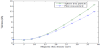
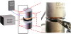
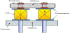
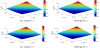
This work proposes a new measurement approach of the magnetic flux density using the characteristics of magneto rheological fluid which is integrated with a variable resistor [23]. For convenience, it is called a magneto rheological fluid variable resistor (MRF-VR) system. The mechanism of the MRF-VR is based on the interaction between ferromagnetic iron particles of the MRF due to an external magnetic field, which causes its electrical resistance to be field dependent. The electrical resistance of the MRF-VR is field dependent because the external magnetic field causes structural changes in the iron particles of the MRF. Utilizing this salient mechanism, an MRF-VR system is devised with two electrodes, outer housing and MRF. Figure 6 shows the proposed design of the MRF-VR. Two copper plates are attached at the top and bottom of a plastic housing, which is fully filled with MRF. h and Dp are the height and diameter of the plastic housing, respectively, and DMR is the diameter of the contact area between the electrodes and MRF. By varying the dimensions of these three design parameters, many types of MRF-VR with different resistive properties can be fabricated. Figure 7 shows the experimental configuration and a photograph of an MRF-VR system. The resistance is measured using the multimeter, and the electromagnets are fixed opposite each other to generate a magnetic field perpendicular to the MRF-VR. In this experiment, the each resistance value of MRF-VR is determined by numerical mean from five measurement samples. It is also recorded after 90 s to be sufficiently saturated, and the experimental results are shown in Figure 8. The initial (maximum) values for the two MRFVRs are 104 and 17.58 M W and the final (minimum) values are 4.46 and 2.09 M . These results reveal a large variation in resistance as the contact area increases. This is because, when the contact area is larger, more electrons can easily pass the MRF through the higher number of iron particle bridges generated between the two electrodes. From the results, it has been observed that that the proposed sensing method is very effective in measuring the magnetic field using resistance variation of MR fluid.
3.4 Tactile display sensor
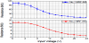
A novel type of tactile display is designed in [24] utilizing magne to rheological fluid which can be applicable for a robotic system in minimally invasive surgery (MIS) to provide a surgeon tactile information of touching remote biological tissues or organs. In order to achieve this goal, a tactile mechanism mimicking biological organs is devised by utilizing MR fluids based on force responses of biological organs. Based on force responses of human body, the tactile display is appropriately designed and magnetic analysis is carried out to determine design parameters using finite element method. It is generally known that biological tissues or organs have viscoelastic properties. In order to mimic this feature, this study introduces the MR fluid and rubber diaphragm into the proposed tactile device. The rheological properties of the MR fluid can be adjusted by adjusting the applied magnetic field. The rubber diaphragm is fully filled with the MR fluid and pressurized so as to recover its original shape after deflection. Figure 9 shows the configuration of the proposed tactile display. The proposed device is a typical array type with four pins, but the pin array is supporting an artificial organ. It is made out of a rubber diaphragm whose inside is fully filled with MR fluid. The rheological properties of the MR fluid can be changed by applying input current to the two solenoid coils whose turn directions are opposite to generate same magnetic flux lines. It is remarked that very thin rubber material is used to enhance MR fluid effect. The tactile sensation consists of the palpation force, the texture, temperature, frequency, velocity, depth of impression and so on. Figure 10 represents the measured tactile forces at four adjacent regions according to the applied current at adjacent pins. The applied current is changed from 0 A to 3 A. The four adjacent regions show a similar force distribution. The minimum and maximum values of tactile force are about 0.392 N and 1.392 N respectively. From these results, it can be assured that the proposed tactile display utilizing MR fluid is very reliable.
4. Conclusion
This paper presents a brief review of the various sensors designed using magneto rheological fluid to measure yield stress, direct current (DC), magnetic flux and the tactile sensitivity of the human organs. Since the working principle of yield stress measurement system and DC current sensor are based on the resonant sensor concept, it has advantages such as digital frequency output, good stable performance, high resolution, better reliability and fast response time. The design of MR fluid yield stress measurement system using resonant concept is completely novel and will lead to the new dimension in the development of innovative characteristics equipments. Among the current sensors available in literature, the sensor designed using the recent MR fluid technology provides better performance than the other conventional sensing techniques such as Ohm’s law of resistance, Faraday’s law of induction, Magnetic field sensors and Faraday effect. On the other hand, magnetic flux sensor designed using the electrical resistance property of the MR fluid finds extensive application in magnetism based application. In tactile sensor, the biological organ is imitated by using MR fluids based on force responses of biological substance, which finds wide usage in modern medical surgery and treatment. This paper will inspire the readers to design and implement inventive devices using magneto rheological fluid.
Competing Interests
The authors have no competing interests with the work presented in this manuscript.
Author Contributions
All the authors substantially contributed to the study conception and design as well as the acquisition and interpretation of the data and drafting the manuscript.