


1. Introduction
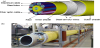
Umbilicals are one of the important facilities in the subsea production system for offshore oil exploitation. The design of umbilicals incorporates the mechanical strength to withstand crushing and tensile loads during handling, installation, and service. The typical configuration of a steel tube umbilical is shown in Figure 1a. It consists of steel tubes, electrical cables, optical fibre cables, fillers, and an inner sheath, which are assembled into an inner core. Steel armour wires are added to achieve the necessary stability. The outer sheath provides protection for the inner components [1]. The mechanical behaviour of the umbilical is obviously affected by various cross-sectional layouts of the inner core, which comprises various components. Some of the technological challenges are ultra-deepwater umbilical installation, high-voltage power cables, and integrated production umbilicals (IPUs). Recently, Heggadal [2] introduced an IPU designed to combine the functions of an umbilical with those of a production or injection flow line and to supply high-voltage power to potential subsea users. Due to their functional intergraded system and cost-effectiveness, IPUs have become increasingly popular in future umbilical systems. For the development and application of IPUs in subsea transformation systems, there are no efficient, well-defined design methods that can provide accurate predictions of the effects of the environmental and operational conditions with varying design parameters in the initial design stages.
The mechanical behaviour of the umbilical is obviously affected by various cross-sectional layouts in the inner core, which in current industry practice comprises various components. Only general considerations that provide qualitative guides for the layout design are presented in the specifications of ISO 13628-5. The dynamic steel tube umbilicals used in deep-water and ultra-deep-water applications are subjected to large tensions and cyclic bending loads during operation. The layers experience significant deformation and contact forces if the cross-sectional layout is not properly designed. To improve the structural performance, tension resistance, and fatigue resistance of the umbilical, the cross-sectional layout must be optimised to achieve lower contact forces and deformation. The IPU system should maintain the temperature in the flow line through a combination of thermal insulation and active heating. It is therefore necessary to evaluate the thermal characteristics of a largebore central pipe and the polyvinyl chloride (PVC) matrix, the various metallic tubes for heating, the hydraulic and service fluids, and the electrical and fibreoptic cables.
Most existing research activity for the design and analysis of umbilicals has focused on the structural design of the steel armour wires [3] and mechanical analysis of a given crosssectional layout. Finite element models (FEMs) based on macro-elements have been used for the cross-sectional analysis. Recently, finite element analysis (FEA) based on commercial software was introduced to the crosssectional analysis [4,5]. However, not much effort has been made on the design and analysis of the cross-sectional layout. In particular, structural considerations have seldom been included in the layout design process, making it difficult for cable designers to give a reasonably efficient cross-sectional layout for complex umbilicals that include multiple types of components. There is insufficient existing research on the IPU cross-sectional design and design procedure.
The objectives of this study, therefore, were to provide the design analysis procedure and investigate the thermal characteristics of the profiled IPU cross-section when it was subjected to installation and operational conditions as part of the proposed design analysis procedure. Thermal analyses were performed to ensure that the cable design complied with the specifications and was suitable for its operational conditions. A detailed numerical analysis (FEM)- based parametric study was carried out with the aim of developing a design procedure and making recommendations for an optimal IPU umbilical system. The insights offered from the modelling techniques and analysis procedures presented in this study should be very useful and practical in the design of subsea umbilical systems.
2. Cross-section Design Analysis Procedure
In this section, the proposed cross-sectional design procedure for IPUs (Figure 2) is summarised; it consists of thermal analysis and structural response analysis, for the determination of an optimised cross-section based on various numerical analyses. Dynamic and fatigue analysis should be carried out to evaluate the fatigue properties of the umbilical system given the anticipated installation and environmental loads and to establish the maximum allowable span lengths. The umbilical is designed for immersion in seawater for its specified design life. Consideration should also be given to storage before installation, exposure to service fluids, the seabed and topside environments, and the dynamic conditions imposed within the freehanging regions. According to the service environment, the design parameters can be categorised by temperature range, maximum working load, minimum breaking load, minimum bend radius, and dynamic service life [2].

The cross section of an umbilical can include various items, such as steel tubes for transporting hydraulic and other fluids, electrical cables, heating pipes, fibre-optic cables, steel rods or wires for strength capacity, polymer layers for insulation and protection, and polymer fillers to fill in the spaces between the components and keep them in place and within certain temperature ranges. IPU system are designed to combine the functions of an umbilical with those of a production or injection flow line, and to supply high-voltage power to potential subsea users. The temperature in the flow line is maintained by a combination of thermal insulation and active heating. Therefore, an analysis of the effects of temperature on the IPU components and interface materials is necessary
IPU systems require a new design analysis that includes global riser analysis, fatigue analysis, a corrosion and hydrogen-induced cracking assessment, structural analysis (production pipe, topside, and subsea termination), reeling analysis, reel/trawler interaction, and on-bottom studies. They must also undergo mechanical material tests of fatigue and corrosion in the basic test stage, fabrication and closing test, STS injection test, QC test and FAT, preinstallation and post-installation tests in the fabrication test stage, and external hydrostatic, impact, model tension, reeling and straightening trials, stinger roller trial, repair trial, vessel trial, system test, and dynamic riser full-scale testing in prototype test [6,7].
Preliminary electrical cables for the design of electrical components should be considered in the power transmission circuit model analysis. Cross-sectional sizing and configuration design should be considered in the electromagnetic analysis and electromagneticthermalcoupled analysis. This stage yields the initial cross-sectional design on the basis of the electrical configuration with thermal and magnetic effects. This initial cross-section can be used as a starting point for the preliminary component mechanical design based on the thermal response and structural response analysis, as shown in Figure 2. The proposed definition of the cross-sectional design was carried out in a two-step cross-sectional design analysis based on the electrical and structural analysis.
3. Thermal Characteristics by Numerical Simulation
3.1 Object IPU
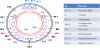
Heggadal [2,8] presented an IPU system in which the flow line and the umbilical were combined in one single line. The IPU cross section consisted of the elements shown in Figure 3. A 10-3/4-in flow line with a three-layer polypropylene coating around the flow line contained an annular-shaped PVC matrix that kept the spirally wound umbilical tubes and cables in place and provided thermal insulation to the flow line. Embedded in the PVC matrix, but sliding freely within it, were various metallic tubes for heating and signalling, and highvoltage cables for powering the subsea injection pump.

3.2 FEM for Thermal Analysis
The thermal insulation properties of the IPU were determined by state-of-the-art FEA, which was carried out to verify the thermal design. ANSYS FEA was used to calculate the heat transfer characteristics of the IPU cross-section. FEA is the most refined method of those currently available and is believed to provide the most accurate solutions. However, it is important to realise that the FEA modelling technique applied must be capable of representing the actual structural behaviour associated with factors such as the geometric and material nonlinearity, boundary conditions, loading conditions, and mesh size.
A number of analyses were performed to simulate heat loss in different media flowing through both ends of the IPU. The use of integrated heating tubes, flow lines, and seawater conditions were also been investigated. Steady state and transient flow line process simulations were performed with the ANSYS workbench. To simulate the true structural and thermal behaviour of the IPU, it was necessary to pay attention to several considerations. As the various material and composite elements in the cross-section were subjected to the characteristic effects of thermal expansion and heat transfer, the element chosen had to be capable of modelling these thermal expansion phenomena and their associated behaviour. A preliminary mesh convergence study of the developed FEM was carried out on the cross section. The parameter used in the convergence study was the model steady-state temperature. The analysis started with a number of large elements. The element size was then reduced to determine the element size required for convergence. The convergent element size observed in the trial runs for an appropriate cross-sectional FE model is shown in Figure 4.

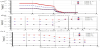
Figure 5 shows the results of the transient thermal analysis, in which 15-mm and 50-mm mesh sizes were compared at various positions. A temperature of 70°C in the flow line was used to verify the FEM in extreme conditions. The total number of nodes and elements were 189,675 and 40,210, respectively, which were determined on the basis of a convergence study shows in figure 6. The transient thermal analysis was computed over 10 days and a steady state of around 6.93 days was reached, as shown in Figure 7.


3.3 Details of the parametric study
Although various parameters and operational scenarios were available, five scenarios were selected for the flow line sensitivity study and three temperatures in the flow line were considered for the effects of the heating pipes, as shown in Table 2. To measure the effects of heating the IPU cross-section, the temperatures of the fluid in the flow line, power cables, and heating pipe were monitored, as shown in Figure 7. M1, M2, and M3 are located along the power cable and the general service line from the centre of the cross-section. Flow line temperatures of 20°C, 30°C, and 40°C were considered. A thermal analysis of the IPU FEMs was undertaken first, followed by a steady- state analysis. The steady-state temperatures of the cross-section of the IPU were obtained from the first analysis. The second analysis provided the thermal response characteristics. The thermal strain and stress and deformation corresponding to the various failure modes were visualised. However, the thermal steadystate analysis was only carried out for the effect of the cross-section design analysis.

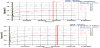
Figure 8 presents the temperature distribution curve for the flow line sensitivity in each monitoring line. It can be seen from these curves that when small electrical power cables were used, or no cables were used, the temperature increase provided by an increase in the heating cables was comparatively small near the flow line (0.8 m from the centre of the cross section). However, this temperature sensitivity became more significant as the power cables’ heat source moved further than 0.8 m from the metallic shield (approximately 0.8 m to 0.9 m).

Figure 9 presents the curves for the temperature versus the distance from the centre of the IPU cross-section, with varying temperature and number of heating pipes. There was a sensitive response between 0.65 and 0.8 m, depending on the temperature of the flow line. However, it was not very sensitive between 0.8 and 0.9 m along the power cable and service line points (M1 and M3).
3.4 Effect of Cross-section
The effect of temperature on the steady-state thermal behaviour of the IPU cross-section was appreciable in the heating sources, but became gradually more prominent in the best configuration of section elements through the temperature-sensitive region. This result suggests that the heating sources (power cable, heating pipe, and flow line) are important in the optimisation of IPU cross-sections. The material properties of the sensor and control line were changed by the thermal effects of the heating cables, power cable, and flow line. These changes are remarkable, considering the deep-water conditions in the design of the IPU cross section.
3.5 Concluding remarks
The objective of this study was to investigate the effect of temperatures differences on the design of the thermal characteristics of a profiled IPU cross section subjected to installation and operational conditions. Based on the limited results obtained for the IPU cross-section, it can be concluded that thermal analysis is useful for the optimal design of IPU cross-sections in terms of computational effort and resulting accuracy. Further studies of nonlinear structural behaviour and electromagnetic-thermal coupled analyses in deep-water conditions are still needed.
A detailed numerical analysis (FEM)-based parametric study was carried out to develop design procedures and make initial recommendations regarding the optimal IPU system. The design procedure presented in this paper will provide assistance to the industry in the design and analysis of subsea IPU systems. The insights offered by the modelling techniques and analytic procedures presented in this study should be very useful and practical in the design of subsea umbilical systems.
Competing Interests
The authors declare that they have no competing interests.
Author Contributions
All the authors substantially contributed to the study conception and design as well as the acquisition and interpretation of the data and drafting the manuscript.