


1. Introduction
Piezoelectric ceramics, polymers and composites are widely used in sensors and actuators in the field of smart materials and structures [1- 3]. With an increasing concern about global warming, the direction of research has changed slightly from just sensors and actuators to an interest in extracting and storing energy from the environment [4, 5]. Some investigations have also focused on the design of self-powering, self-sensing and self-controlling devices. Recently, Wang and Inman [6] examined the concept and design of a multifunctional composite sandwich structure for simultaneous energy harvesting and vibration control. They proposed the glass fiber reinforced composite materials with lead zirconate titanate (PZT) harvester, PZT sensor and PZT actuator, and studied the configurations, locations and operating modes of PZT materials for optimal power generation.
Lead oxide-based ferroelectrics, especially PZT, exhibit high piezoelectric properties. Due to lead toxicity, however, the introduction of legislation in Europe to limit the usage of lead in automotive and electronic products has led to a worldwide search for lead-free compounds [7]. BT (BaTiO3) is one of the most widely investigated lead-free ceramics. Recently, BT-based piezoelectric ceramics have been prepared, and compared with commercial hard PZT materials [8]. Although many researchers are developing the multifunctional composites using PZT materials, few of the BT-based multifunctional composites have been investigated.
In this paper, we discuss the detection and response characteristics of BT unimorph cantilevers with sensing, grounding and driving electrodes under AC electric fields. A three-dimensional FEA was performed to predict the deflection and output voltage in the BT unimorph cantilevers. The deflection and output voltage were also measured, and numerical results were compared with measured values. The deflection, stress, output voltage and output power were then examined in detail.
2. Analysis
2.1 Basic equations
Equations of motion and Gauss’ law are given by
where σij is the stress tensor, ui is the displacement vector, ρ is the mass density, Di is the electric displacement vector, and a comma denotes partial differentiation with respect to the coordinates xi (i =1,2,3)or the time t. We have employed Cartesian tensor notation and the summation convention for repeated tensor indices. Constitutive relations can be written as
where εij is the strain tensor, Ei is the electric field intensity vector,
and sijkl, dkij and
The relation between the strain tensor and the displacement vector is given by
and the electric field intensity vector is
where ϕ is the electric potential. The constitutive relations (3) and (4) for piezoelectric ceramics poled in the x3 -direction are given in Appendix A.
2.2 Finite element method
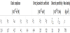
A unimorph cantilever constructed of BT layer and Cu shim is shown in Figure 1a. Let the coordinate axes x = x1 and y = x2 be chosen such that they coincide with the interface and the z = x3 axis is perpendicular to this plane. The origin of the coordinate system is located at the center of the bottom left side of BT layer, and the edge at x = 0 is clamped. The geometry and dimension are shown in Figure 1b. BT layer of length 50 mm, width 25 mm and thickness 1 mm is added to the upper surface of Cu shim of length 50 mm, width 25 mm and thickness 0.5 mm. The total thickness is 1.5 mm.
BT layer has sensing, grounding and driving electrodes. The sensing and driving electrodes are located at the center and outer parts, respectively. To suppress coupling, there is a grounding electrode between these two electrodes [9]. On the other hand, only a whole grounding electrode is located on the opposite side.
We performed three-dimensional finite element calculations. The commercial software ANSYS with 3D eight-node elements was used in the analysis. For simplicity, the electrode layers were not incorporated into the model. This is because the thickness of the electrode layer is much smaller than the thickness of the BT layer. The electric potential on the top driving electrode surface equals the applied voltage ϕ = V0exp(iωt), where V0 is the amplitude of applied voltage and ω is angular frequency. The top and bottom grounding electrode surfaces are connected to the ground, so that ϕ=0. The deflection and internal stress for the cantilever were then calculated. The output voltage of sensing electrode was also predicted.
3. Experimental Procedure
The unimorph cantilever was fabricated using BT layer (NEC/Tokin
Co. Ltd., Japan) and Cu substrate. Table 1 lists the material properties
of BT layer. Elastic compliances s11, s33, direct piezoelectric coefficients
d31, d33 , dielectric permittivity
An AC voltage was applied to the driving electrode surface of the BT layer, while the grounding electrode surfaces were earthed. The amplitude of tip deflection wtip of the cantilever was measured with a laser displacement sensor (LK-G10, KEYENCE, Co. Ltd., Japan). Output peak voltage Vout of the sensing electrode was also measured for the cantilever using an oscilloscope (GDS-1062A, Good Will Instrument Co., Ltd., Japan). Then, the output power Pout from the cantilever can be calculated using the output peak voltage Vout and load resistance R.
4. Results and Discussion
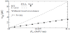
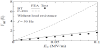
Figure 2 shows the amplitude of the tip deflection amplitude |wtip| as a function of AC electric field amplitude E0 for BT unimorph cantilever without load resistance at frequency f = ω/2 = 50Hz. The solid line represents the value of the tip deflection predicted by the FEA, and the solid circle denotes the measured data. For comparison, the predicted deflection for PZT C-203 unimorph cantilever (Fuji Ceramics Co. Ltd., Japan) is also shown as dashed line. The material properties of C-203 are listed in Table 2, and the coercive electric field is about 2 MV/m. Note that the tip deflection for PZT C-203 unimorph cantilever was predicted considering domain wall motion [11]. A nonlinear relationship between the tip deflection and electric field is observed for PZT C-203 cantilever. On the other hand, the tip deflection for BT unimorph cantilever increases linearly as the electric field increases, and the results of the FEA are in excellent agreement with measured data. It is therefore expected that the domain wall motion may not occur in the BT layer under AC electric fields. The formation of defect complexes during manufacturing of the BT layer are thought to reduce the mobility of ferroelectric domain wall. Figure 3 shows the predicted and measured output peak voltage Vout of the sensing electrode as a function of E0 for BT unimorph cantilever without load resistance at f = 50 Hz. Also shown is the predicted data for PZT C-203 unimorph cantilever. The output peak voltage for BT unimorph cantilever increases linearly as the electric field increases, similar to the tip deflection. It can be seen that agreement between FEA and test is fair. The results show that the output voltage is capable of self-powering or self-sensing.

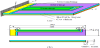
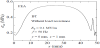
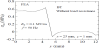
The variation of normal stress amplitude |σxx| along the length direction is calculated for BT unimorph cantilever without load resistance at a chosen point (y = 0 mm and z = 1 mm here) and the result is shown in Figure 4. All calculations were done for E0 = 0.1 MV/m at f = 50 Hz. The output peak voltage of the cantilever under E0 = 0.1 MV/m at f = 50 Hz is about Vout = 2.0 V. A high normal stress occurs near the center of the BT unimorph cantilever. Figure 5 shows the variation of normal stress amplitude |σxx| along the width direction for BT unimorph cantilever without load resistance at x = 25 mm and z = 1 mm. All calculation was done for E0 = 0.1 MV/m at f = 50 Hz. There is a substantial difference in the stress near the edge of driving electrode. It is noted that the normal stress for the sensing part is much higher than that for the driving part. The results for the evaluation of stresses may help multielectroded BT cantilever designers to estimate the fracture risk and to optimize in-service loading conditions.
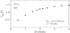
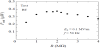
The variation of the measured output peak voltage Vout of the sensing electrode with changing load resistance R is shown in Figure 6 for BT unimorph cantilever under E0= 0.1 MV/m at f = 50 Hz. The output voltage increases with load resistance. Figure 7 shows the output power Pout for BT unimorph cantilever under E0 = 0.1 MV/m at f = 50 Hz. The output power tends to increase with load resistance reaching a peak and then to decrease in magnitude. It can be seen that the optimal load resistance for BT unimorph cantilever is about 2 MΩ.
5. Conclusion
This paper presents the results of numerical and experimental study in the BT unimorph cantilevers with sensing, grounding and driving electrodes under AC electric fields. On the basis of the study conducted, the following conclusions seem to be justified.
- The tip deflection of the cantilever and the output peak voltage of the sensing electrode increase linearly without domain wall motion as the AC electric field amplitude increases.
- The stress in the sensing part of BT unimorph cantilever is significantly higher than that in the driving part for the same AC electric fields.
- The output power in the sensing electrode of BT unimorph cantilever under 0.1 MV/m can achieve about 0.4 μW at 50 Hz.
By knowing how the sensing and driving electrodes interact, we can design self-powering, self-sensing and self-controlling devices to achieve particular overall properties. Our present study offers a method for aiding the design of new BT-based multifunctional composites, and provides a basis for refining the real device design in order to reduce internal stresses and increase output voltage and output power.
Competing Interests
The authors declare that they have no competing interests.
Author Contributions
All the authors substantially contributed to the study conception and design as well as the acquisition and interpretation of the data and drafting the manuscript.