


1. Introduction
For the analysis of a deformation to verify the serviceability limit state (SLS) of geotechnical structures, numerical methods have been established in recent years. In this course, more and more complex structures are simulated in ever larger models in 2D and / or 3D. To create each model, a time effort which should not be underestimated is necessary. Thus, it is essential to further develop the numerical methods or the calculation procedures in order to be able to perform ultimate limit state (ULS) investigations by means of numerical methods in the future.
Related to the verification of the overall stability in design approach 3 (DA 3) for slopes, numerical methods already are well accepted. Detailed information and recommendations mainly obtained on the basis of a comparative calculation can be found in [1]. With respect to the present topic, it is noticeable that the verification with numerical methods only refers to one limit state and soil-structure interactions are almost completely disregarded. This is evident, for example, regarding the consideration of structural elements, which usually requires a separate investigation (numerically or even analytically).
Therefore, this paper presents a comparative calculation to investigate the influence of structural elements on the stability of a slope. The basis for this research is the option of the finite element programme PLAXIS 2D to implement Python scripts via a remote scripting interface. In the first section of the paper, the strength reduction method is simulated using a self-developed Python script to be verified by means of comparison with numerical and analytical methods. Subsequently, the Python script is extended, such that structural elements can also be considered. Further comparative calculations are carried out using the extended Python script. Based on this, a safety factor is defined and compared with results of analytical analyses. Finally, the knowledge gained is summarized and the use of the implemented technique for future research questions is discussed.
2. State of the Art
2.1 Strength reduction method
The basis for the investigations presented in this paper is the wellknown strength reduction method [2] applied in the finite element method (FEM) in the program PLAXIS 2D [3].
Besides this approach, it is also possible to investigate geotechnical constructions with novel methods such as mathematical topology optimisation in the form of discontinuity layout optimisation (DLO). Here, discontinuities in a body are determined in the case of failure as well as the associated upper limit load for plasticity problems [4-6].
Another approach is to use mesh-free methods to determine shear bands in the soil [7,8]. This is related to the fact that in FEM the quality of the results depends on the discretization of the finite element mesh. Using mesh-free methods, this disadvantage is circumvented and the shear bands are identified as strong displacement discontinuities.
The approaches mentioned before are alternatives to the FEM. In addition, the aim of this paper is to improve the FEM, therefore the programme PLAXIS 2D is used for the presented calculations. Using the strength reduction method the soil’s shear parameters are successively reduced until a limit state is reached where equilibrium no longer occurs. This limit state is specified by a Mohr-Coulomb failure criterion. The method was established in geotechnical engineering in recent years as it is widely implemented infinite element codes to be used for the ultimate limit state analysis of slopes, dams and hillsides. The safety factor calculated by this method is characterized by the quotient of the characteristic shear parameters and the reduced shear parameters representing the failure state.
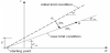
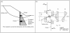
As defined by the factor of safety, the shear parameters are reduced by a uniform factor. For illustration, a soil’s limit state for tan φ' and c' is shown in Figure 1. By reducing the shear parameters, a new limit state condition is defined. This procedure is pursued until a state of failure is reached and equilibrium can no longer be determined.
In the meanwhile, many comparative calculations with traditional analysis methods in geotechnics have shown that the strength reduction method is a capable alternative [9,10]. However, there is still a need for research, for example with respect to the consideration of structural elements. According to the current recommendation of the Working Group 1.6 "Numerics in Geotechnics" of the German Geotechnical Society (DGGT), structural elements require an additional separate consideration when investigating stability only using a classical φ - c reduction [1].
Therefore, it has already been suggested to successively reduce the decisive parameters of the structural elements similar to the φ - c reduction [11,12]. Possible parameters to be reduced beside the soil’s shear parameters are, for example, the maximum compressible strut load or the maximum bending moment of a retaining wall. Another possibility, for example in the case of steel components, is to reduce the yield strength fy, since this is linearly related to the resistances of the structural elements. In this paper, the possibility of reducing the diameter of piles is investigated with respect to a practical example, since this does not only consider the relevant material parameters, but also the stiffness conditions and the soilstructure interaction.
2.2 PLAXIS remote scripting interface
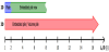
The comparative calculations presented in this paper are simulated using the FE program PLAXIS 2D. To automate the variation of parameters for the comparative calculations, the program offers a server-based programming interface (API - Application Programming Interface) based on the Python programming language [3]. The general procedure for the use of the remote scripting interface is shown in Figure 2.
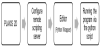
Via the connection to the remote scripting server, a wrapper is opened to edit the Python script. Afterwards, it is possible to control the input and / or the output program of PLAXIS using the script. The Python script contains the commands that are normally entered manually in the command line of the program. This makes it possible to extend the commands with loops, function, etc. Therefore, the remote scripting reference is a versatile and powerful tool.
3. Comparative Calculation
In this section, the implemented strength reduction method programmed in a Python script will be analysed and verified by means of comparing the results with results received out of the established φ - c reduction in PLAXIS as well as analytical methods, such as the limit equilibrium method.
Investigating the example of a homogenous slope, the soil’s shear parameters are successively reduced using a loop in the Python script. This process is repeated until the program can no longer find a calculated equilibrium. The safety factor is derived based on the shear parameters at collapse. The calculated safety factor is compared with the safety factors calculated by the aforementioned methods. On this basis, the verification of the Python script is received.
In [13], the functionality of the Python script for the strength reduction method has already been verified for a cohesionless soil. Therefore, in this paper, the method is verified for a cohesive soil such that the cohesion is reduced parallel to the friction angle.
3.1 Model information
The geometry of the investigated slope as well as the FE mesh used are shown in Figure 3. The slope has a height of H= 10.0 m. The safety factors are calculated for varying slope angles between β = 15°-30°. In order to guarantee a sufficient mesh fineness in the area of the potential critical failure circles, the mesh is locally refined and overall a very fine mesh is used to overcome mesh dependency of the problem.
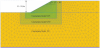
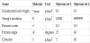
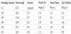
Table 1 shows the soil parameters considered in the comparative calculation. The soil is only affected by self-weight loading. Due to this, a rather simple constitutive model with a limit condition according to Mohr-Coulomb is sufficient for this study.
3.2 Methods for calculating the safety factor
The strength reduction method programmed using the Python scripting utility is verified by comparison with well-established methods. In this research, the following three methods are investigated:
- Method 1: analytical, limit equilibrium method
- Method 2: Python script
- Method 3: φ - c reduction
For slopes with cohesive soils, the slope stability calculation is often performed using the limit equilibrium method according to Bishop [14] which in the present paper is done using the GGU-Stability program (method 1).
Regarding the numerical calculation, a safety calculation phase is simulated in PLAXIS starting from the primary stress-state (initial phase). In this phase, the Python script (method 2) is executed, such that the shear parameters are successively reduced. The calculation of this phase is performed with further reduction of the shear parameters until failure is reached. Based on the calculated values (minimum possible shear parameters), the safety factor is determined.
The φ - c reduction implemented in PLAXIS 2D is selected for the comparative numerical analysis (method 3). For this purpose, an automatic safety analysis is performed in the program after the initial phase.
4. Results
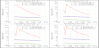
The results of the comparative calculation considering the three previously named methods are shown in Figure 4. In this figure, the abscissa shows the varied slope angles and the ordinate the corresponding calculated safety factors.
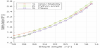
Based on the results, it can be noted that the safety factors calculated with the Python script are almost always a bit larger compared to the safety factors of the program-internal φ - c reduction. For most parts, the results correlate with the results of the analytical limit equilibrium method. In addition, it can be noted that the deviation between the results of method 2 and 3 is less than 4%. The results are in line with the results for a cohesionless slope in [13] where the Python scripting approach was already verified for cohesionless soil. Since the deviation is also small in the present case, the Python script can also be considered verified for the analysis of cohesive soils.
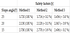
In addition, the Table 2 shows the calculated safety factors for selected slope angles and their deviation from the results obtained using the analytical approach, which is selected as the reference method for this purpose.
5. Structural Elements in Slopes at Risk of Failure
In this section, the influence of structural elements implemented in a slope with respect to limit state analysis is investigated using numerical methods in the two-dimensional case. The structural elements investigated are dowels which are modelled with a defined out-of-plane distance (see Figure 5). For modelling of the dowels embedded beam row (EBR) elements are chosen [3].
To identify the critical diameter in which the stability of the slope is just still present, the Python script discussed before is extended. The dowel’s diameter is successively reduced for varying shear parameters. This procedure is analogous to the φ - c reduction. Thus, at the end of this section the transferability of the pile diameter’s reduction to a possible stability analysis, as it is already handled for slopes with the φ - c reduction, is checked on the basis of the results.
It should also be noted that the present calculations are carried out with characteristic values. No partial safety factors are taken into account in either the analytical or the numerical calculation.
5.1 Model information
For the studies presented in this paper, a slope with a height of H= 5.0 m is modelled. The slope angle is β= 32.5° and the EBR elements are arranged vertically in the middle of the slope. The length of the EBR elements is set to L= 5.0 m. In addition, the slope is loaded by a uniform line load (p= 5 kN/m2).
The following Figure 6 shows the geometry of the slope to be analysed as well as the loading conditions. The FE mesh used is also shown, for which a local mesh refinement is carried out as already discussed regarding the homogenous slope investigated before.
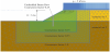
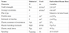
The soil parameters applied in the numerical study are depicted in Table 3. Two different material sets are used; see Figure 6 and Table 3. To ensure that the critical slip circles are within the slope and that the structural elements have a restraining effect, an infinitely stiff soil is considered below the slope (material set 2).
Using EBR elements, it is possible to model beam elements such as piles, anchors and soil nails out-of-plane with a centre distance perpendicular to the model surface in a 2D simulation [3].
The functionality of the EBR elements was already tested in [15] using comparative calculations. It was shown that the centre distance between the piles has a decisive influence on the result of the calculation. Therefore, a maximum distance of up to 6-8 times the pile diameter is recommended for the centre respectively out-of-plane distance (see Figure 7). To investigate this behaviour more closely, the centre distances are varied in this paper.
In addition, the values for the skin, base and lateral resistance of the EBR elements are specified directly. The parameters must be set carefully, as they influence the calculation result. In order to exclude the influence of an automatic determination of these values, they are defined with fixed values and not varied: Tskin= Tlat= 1000 kN/m and Fmax= 1000 kN.
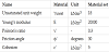
A pile is selected as option for the EBR elements. Steel is used as the material so that the plasticising can be considered. The material behaviour is defined as elastoplastic, which makes it possible to include the maximum plastic bending moment Mp and axial force Np in the material’s definition. These parameters depend on the diameter of the EBR elements such that this value is chosen is to be reduced in this study to identify the limiting pile diameter before failure. The following Table 4 shows the material parameters used:
5.2 Calculation procedure
As a first step, the slope’s shear parameters are reduced without the addition of structural elements until a failure condition is reached. This makes it possible to determine the limiting parameters at which the slope is no longer stable without additional elements. The present slope fails for the following parameters: and .
Starting from this point, the shear parameters are reduced by one percent per each step. In these calculations the EBR element is included. Further reduction of the shear parameters allows to determine the range in which the load-bearing capacity of the slope only depends on the material parameters of the structural elements. Out of this, it can be concluded that the shear parameters can be reduced by a further 20% based on the shear parameters at failure due to the support of the structural elements. The slope, including the supporting effect of the structural elements, fails at: and .
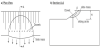
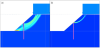
Afterwards, failure of the soil above the elements occurs, such that it is no longer possible to achieve a state of equilibrium, regardless of the choice of the diameter of the structural elements. For illustration, the incremental deviatoric strains of two failure mechanisms are shown in Figure 8. On the one hand, the Figure 8a describes the state with shear parameters in the range where failure only depends on the dowel’s parameters (failure of the dowel). And on the other hand, the Figure 8b shows slope failure above the dowels. This is due to the fact that the shear parameters have been reduced to such an extent that the dowels no longer have a stabilizing effect.
Furthermore, the range of shear parameters in which the stability exclusively depends on the material parameters is investigated in more detail: and Regarding this range, the diameter of the structural elements can be reduced until failure occurs. A safety factor regarding the internal stability of the dowels can be defined by using the starting diameter and the limit diameter analogously to the afore discussed φ - c reduction (method 1). Failure is significantly influenced by exceedance of the plastic bending moment which depends on the dowel’s diameter to the power of three for solid cross-sections. Due to this, a safety factor is defined for the dowel with a circular solid cross-section:
To verify the safety factors calculated this way, the results are compared with two analytical methods. For validation purpose, the safety factors of all investigated methods are compared with each other.
With the widely used analytical program GGU Stability (method 2) it is possible to implement vertical dowels within the slope [17]. The decisive failure circle is calculated according to the limit equilibrium method. Therefore, the dowel is considered by applying an additional retaining component in the calculation model. This retaining component can either result from the earth resistance or from the design force to be applied. The larger component becomes decisive (see Figure 9a).
The second analytical method used for validation purpose is the dowel theory (method 3) according to Huder [18,19]. The dowel is considered by application of a shear force as an additional retaining force. The shear force results from the assumption that the pile fails due to bending failure. As a result, plastic joints form above and below the critical sliding circle in the limit state. Hence, a stabilising shear force resulting from the deformation can be determined for the dowel up to the failure point (see Figure 9b).
6. Results
The following Table 5 shows the results for a fixed centre distance between the dowels of Lspacing= 2.5 ∙ D as an exemplary case. The first column of the table shows the percentage reduction of the shear parameters which is also plotted on the x-axis in the following diagrams (see Figure 10). The reduction is always based on the shear parameters at failure of the slope without reinforcing dowels (here: and ). The calculated safety factors are plotted on the ordinate considering a logarithmic scale.
The results in the diagrams of Figure 10 show that the calculated safety factors deviate from one another according to the three methods investigated (Method 1. - reduction of the diameter in PLAXIS 2D, Method 2. - limit equilibrium method in GGU Stability and Method 3. - dowel theory). The reason for this is that different forms of failure are examined in the respective calculation methods. Accordingly, the various forms of failure are discussed below and placed in the context of the calculation results.
- Reduction of the diameter in PLAXIS 2D
Regarding the studies with diameter reduction, the soil at the base of the slope is modelled with an infinite stiffness (see material set 2 in Table 3), simulating a fixed restraint of the dowels. In addition, the shear parameters of the soil are reduced beyond the failure case ( and ). Due to this, a ground failure has already occurred without the supporting effect of the dowel, so that the stability of the overall system depends exclusively on the parameters of the dowel. As a result, the entire system fails only by exceeding the plastic moment of resistance of the dowel (bending failure). A check of the calculation results shows that shear failure does not become decisive.
Furthermore, it is shown that in the transition area between ground failure and dowel failure (i.e. at i > 0.95) no clear safety factors can be calculated. This aspect is due to numerical uncertainties during the calculation considering two different failure mechanisms possible to occur under the conditions investigated.
- Limit equilibrium method with GGU Stability
With regard to the applicability of the analytical method implemented in GGU Stability, it can be stated that it is the only method in which the safety factor reached values below 1.0. This is due to the fact that the total stability of the slope is investigated considering a combination of soil and dowel. The ratio of driving and resisting forces is determined in the form of the utilisation factor, or the reciprocal of this as a safety factor. The supporting effect of the dowel is considered in the form of an additional resisting force. An examination of the dowel with regard to bending failure is not part of this method. It can therefore be assumed that the analytical method can be used to determine the limit state of failure of the ground (GEO). However, it should be noted that due to the necessary assumptions and simplifications the analytical approach cannot represent the soilstructure interaction as realistic as a finite element simulation for example.
- Dowel theory
Furthermore, the results in Figure 10 show that the dowel theory produces highly conservative results and the safety factor is well on the safe side. This is related to the fact that the dowels are verified with regard to possible shear failure. It is questionable whether plastic joints will form for diameters as small as those investigated in the present study. Therefore, it remains to be stated that the dowel theory is not applicable for such small diameters. In particular, the numerical calculations have shown that the dowel fails primarily due to bending.
7. Summary and Outlook
In this paper, three different methods for the determination of a safety factor for homogenous slopes in cohesive soils are presented and compared with each other within the scope of comparative studies. The calculations demonstrate that with the help of the Remote Scripting Interface in PLAXIS 2D a Python script can be developed to carry out a strength reduction method.
Subsequently, the script is extended to include structural elements. For this purpose, a stability-endangered slope is modelled in which embedded beam row elements are implemented for stabilisation. Using this model, a range of shear parameters was identified in which the slope is only stable due to the stabilising effect of the structural elements. In this range ( and ), the diameter of the structural element (dowel) is reduced independently of the soil and based on this a safety factor SFEBR is defined. By reducing the diameter, the soil-structure interaction, that can only be considered realistically by means of numerical methods, is included in the safety definition.
However, the comparison of the methods within the context of a second parameter study considering numerical as well as analytical methods results in differentiated safety factors. The reason for this is that different failure mechanisms are investigated in the three methods investigated.
For the numerical investigation with PLAXIS 2D and the reduction of the diameter in a slope at risk of failure, some boundary conditions are considered, such as the infinitely stiff subsoil. Due to this, the dowel is forced to fail due to the plastic moment of resistance being exceeded, thus due to bending failure. A shear failure does not become decisive. In addition, ground failure can also be excluded, as this has already been proven due to the reduction of the shear parameters of the soil in the slope without dowels.
In contrast, the analytical method according to the limit equilibrium method using the GGU Stability program investigates the entire ground failure of the slope. There, the dowel is only considered in the form of an additional resisting force. The safety factor is defined by the ratio of the driving and resisting forces of the critical sliding circle. Accordingly, the total failure is determined here on the basis of simplified calculation models.
The dowel theory assumes a shear failure of the element due to the formation of plastic joints. On the basis of this, a shear force is determined which, analogous to the limit equilibrium method, is considered as an additional resisting force. Due to the assumption of a shear failure, this is a conventional calculation method and the safety factors are significantly larger compared to calculations using the limit equilibrium method.
Furthermore, the suitability of the diameter reduction method for determining a safety factor has shown that the development of a holistic analysis for determining slope stability as well as the stability of other geotechnical structures with numerical methods appears to be important. For this purpose, it is important that, in addition to the diameter, the shear parameters of the soil are also reduced to an equal level. Therefore, the focus of future research lies on the development of a method to simultaneously reduce all relevant parameters (shear parameters of the soil as well as structural resistance of dowels) to identify the most relevant failure mechanism of the reinforced slope for example.
In this context, the implementation of partial safety factors in the numerical design approach will take an important role. Regarding the strength reduction method, the shear parameters of the soil are to be assigned to the design approach 3 (DA 3) and the reduction of the structural element’s diameter must be assigned to the design approach 2 (DA 2). In the classical analytical detection methods, the verifications are strictly separated from each other. This strict separation is not feasible using numerical methods and is therefore worth to be investigated in future research.
Another aspect for future research is to enhance the presented methods to three-dimensional models. For this purpose, further comparative calculations are carried out with the numerical FE program PLAXIS 3D. Special attention should be paid to the determination of the safety factor for small out-of-plane distances.
The knowledge gained from these issues is then to be further applied to excavation pits. The aim is to develop an integral stability analysis of excavation pits. Therefore, the material parameters of the structural elements have to be reduced analogous to the φ - c reduction method. This procedure should allow the identification which component fails first or which verification is decisive for the analysis.
Competing Interests
The authors declare that they have no competing interests.