


1. Background
1.1 Current exoskeletons
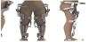
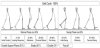
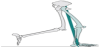
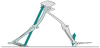
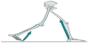
This work presents a more comprehensive assessment of the use of natural materials in orthopedic application and it is a follow up on a previous paper which dealt with the use of low-cost material for exoskeletal application. Gait is fundamental to the quality of life [1]. Gait is essential to basic activities of daily living (ADLs) to one’s ability to carry out functional tasks for independent living. For person’s living with gait and balance disorders, gait abnormality can limit quality of function and create barriers on activity performance and participation [2]. This is particularly significant for the lower extremity (LE) amputee, where the major limitation is often the difficulty with walking [2,3]. In addition, the cost of prosthetic devices essential to restore function in people with gait dysfunction is not affordable to many. Depending on the type of prosthetic leg, the cost of prosthesis can typically range from $5,000 for a basic prosthetic leg to above $70,000 for an advanced computerized prosthetic leg and exoskeletons, and the prosthesis may only last anywhere from three to five years before requiring replacement related to conditions of wear and tear [3]. While continual adjustments and numerous replacements will be needed during the lifetime of the amputee; for the patient without health insurance, the long-term costs associated with prosthetic care may not be affordable. While prostheses are artificial devices used to replace missing body parts, exoskeletons work in parallel with the body to assist the user in their movements. Although both devices are primarily used for rehabilitation purposes, Exoskeletons can also be used as safety equipment. The exoskeletons that are used for safety equipment, assist workers in performing hazardous jobs with minimal injuries [4]. When used for rehabilitation purposes, the individuals in question are usually suffering from debilitating neurological or limb pathologies lacking sufficient strength, power, torque, and endurance [5]. Exoskeletons can be used to target the full body, upper extremities, and lower extremities [6]. Figure 1-4 presents the different types of exoskeletons used for lower extremities, and they are classified as powered, passive, pseudo-passive, and hybrid [5,7-10].

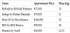
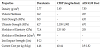
Obviously, exoskeletons enable people with serious mobility issues to leave their wheelchairs behind. The main issue is that the cost of a wheelchair is cheaper than an exoskeleton which is why health insurers don’t see its benefit. When the price of the exoskeletons become comparable to that of a wheelchair then insurance companies will consider these devices for personal use. Physical therapy offices and large companies are the current exoskeleton customers. The high cost of exoskeletons can be attributed partly to the cost of the material it is made out of. Exoskeletons currently available are typically made of Duralumin (Al-2024 T6). Other materials investigated were either too heavy (steel) or too expensive (carbon fiber). In order to replace the current material (Duralumin), it is important that the cost of the new material must be significantly lower, in addition to maintaining the requisite properties for gait. Table 1 contains the cost and mass of the exoskeletons available in today’s market [11-17].
An earlier study by Reed and Kalu, 2015, addressed the usage of natural materials for prosthetic and orthopedic devices in order to substantially reduce their cost [5]. Focusing on the loading requirements of the stance extremity, a comparison of all possible natural materials showed that bamboo with its excellent physical and mechanical properties can suitably replace Duralumin in exoskeleton design [5]. However, to fully consider the usage of bamboo for prosthetic and orthopedic device applications, a comprehensive assessment of the materials response to the external torque produced by the ground reaction force on the joint during the stance phase is necessary. To satisfy this requirement, the material must have high fracture toughness and formability.
2. Kinetics and Kinematics of Walking
2.1 The gait cycle
As shown in Figure 5, in a normal gait cycle the stance and swing phases consists of eight subunits or events [18]. The stance phase is labeled by the contact of the foot with the ground and involves five events, which include initial contact, loading response, mid-stance, terminal stance, and pre-swing. Although there are three basic tasks during gait: weight acceptance, single limb support and limb advancement. However, the specific tasks of weight bearing are carried out by the stance limb. The first 10% of the gait cycle corresponds to the task of weight acceptance at initial contact through loading response. The mid-stance, which occurs between 10% to 30% of the gait cycle is referred to as the single limb support and characterized by the body weight moving over to the forefoot [18,19]. The end of the weight acceptance, known as the terminal stance phase, is reached when the body weight moves anteriorly to the forefoot at 30% to 50% of the gait cycle. The last part of the gait cycle (60% to 100%) is referred to as swing phase, and this has three events, namely: initial swing, mid-swing, and terminal swing. The swing phase is when the foot is not in contact with the ground and is primarily associated with limb advancement. A normal walking gait is dependent on these complex functional tasks being executed with precision.
In addition to all the aforementioned tasks, human locomotion involves the rotation of various joint segments to support, balance, control, and stabilize the body from excessive joint loads occurring during weight-bearing activity [18-20]. Furthermore, 10% of a person’s total body weight is supported at mid-stance of the gait cycle [5]. Therefore, at a minimum, the exoskeleton must be able to endure/ support 10% of a person’s total body weight. This translates to about 80 N, since the average male weighs 80 kg (about 800 N), the lower extremity exoskeleton must be able to withstand at least 80 N [5]. It is necessary to mention that this value can be less than the maximum ground reaction force obtainable, as discussed in later section.
3. Ground Reaction Force
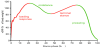
Important to the mechanics of walking is the position of the vertical ground reaction force (vGRF) vector about the joint’s axis [19-21]. The vGRF is used in clinical analysis of gait to represent the forces the body applies to the ground through the foot [20,21]. The force experienced by the ground is dependent on the acceleration of the body weight and is equal in magnitude and opposite in direction to the body weight acting upon it. Soon after initial contact, the progression of force application under the foot can exceed body weight. Since the COM is moving downwards and under some deceleration, a vGRF greater than body weight is needed to decelerate the downward movement of the body [22]. This could result in peak vGRFs that can reach up to 1.2 times the body weight (Figure 6) depending on the direction of the inertial force during the specific events of stance phase gait [19,23]. In fact, these reaction forces are nothing more than the algebraic summation of all body segments mass - acceleration products. The produced inertial force is added to the gravitational force and can be 100% ± 20% of body weight transmitted to the foot forces needed to decelerate and accelerate the body forward [22]. Although fluctuations in inertial forces are highest at loading response and terminal stance, at mid stance, the vGRF is less than body weight resulting from the unweighting and upward momentum of body mass [19]. Since force is a function of mass and acceleration, the vertical acceleration can be up to 20% of gravitational acceleration upwards or downward [22]. To further understand the variations of the vGRFs around body weight, the gravitational, inertial and vGRFs likely contribution to different joint moments at the ankle, knee, and hip during normal gait should be discussed [24,25]. A wellresearched study by Boccardi, Pedotti, Rodano and Santambrogio (1981) analyzed the joint moments occurring at the hip, knee and ankle during stance phase to investigate the effects of the GRF on joint kinetics [26,27]. By utilizing Quasi-static calculations, the researchers concluded that inertial, gravitational, and GRF forces were highest at initial contact and pre-swing phases where the dynamic forces and accelerations of the body are greatest [25-27]. In addition, the study determined that gravity and inertial moments was greatest at the hip joints and relatively low at the ankle during slower walking speeds [27]. Since the extent of the GRF is subject to the foot’s position as it contacts the ground, this is equally true for the center of gravity (COG) of the body. The center of gravity (COG) of a body is the net location of the body's center of mass in the vertical direction and is weighted average of the center of gravity of each body segment. The COG is reported to be 2 inches (5 cm) anterior to the second sacral vertebra [19]; and it is balanced and maintained by foot contact with the ground [18,19]. Although the sequences of motion patterns between the joints are constantly changing during walking, a change in the position of the foot or ankle could greatly challenge the body to provide support at each joint and generate propulsion [20,21]. As the foot becomes part of a closed kinetic chain at heel-strike, an alteration at the foot can result in proximal adaptations at the ankle, knee, hip, pelvis, spine, or the upper extremity to counterbalance the lower limb movement [20,21,25,26]. Conversely, the reactions of proximal joints to maintain COG can translate to a greater dependence on the proximal muscles of the pelvis, hip and knee joints to control stability and support the weight of the head, arms, and trunk (HAT) during lower limb loading [19]. Despite the fact that active rotary torques are common patterns of movement for many joints along the kinetic chain, the distance of the joint from the torso could likely determine the extent of rotation transpiring at each joint [18,19]. A change in foot position can alter the joints axis of rotation and cause different bending moments about the axis. This can lead to the influence of proximal muscle control on distal extremity kinematics and result in alterations in normal movement patterns essential to meet load and balance requirements at the hip and knee joints [2,26]. While a change in body alignment can influence the fluidity and efficiency of a walking gait, the determinants of the arms will respond to counter any excessive COG displacements [18,19,25].
4.1 The determinants of stance phase gait
Pelvic rotation, pelvic tilt, knee flexion in stance phase, foot mechanics, knee mechanics, and lateral displacement of the pelvis are determinants of the gait cycle. These joint actions help to minimize COM excursions to maximize forward progression of the body with the least expenditure of energy [28]. Rotations of the major joints of the lower extremity limbs occur to progress the body forward while providing for weight-bearing support against external torques. Here, brief discussions of the major joint actions are necessary to provide a comprehensive appraisal of materials response. 1) Pelvic rotation: the pelvis rotates medially/anteriorly on swinging leg side. This action essentially lengthens that limb as it prepares to accept weight and help to keep limbs lengthened at lowest point of COM to prevent sudden drop in COM; 2) Pelvic tilt: the pelvis on swing leg (opposite to weight bearing leg) is lowered 4-5 degrees where this action lowers the COM at mid stance; 3) Knee flexion in stance phase: knee flexes 15-20 degrees at initial contact and loading response. This action lowers the COM and reduces the otherwise high vertical elevation at mid stance to decrease energy expenditure. Also absorbs the shock of impact of heel strike mechanics; 4) Foot mechanics: The controlled plantar flexion at initial contact to smooth curve of the dropping pelvis; 5) Knee mechanics: the knee extends at mid-stance, and this action coincides with ankle plantarflexion and foot supination to restore length to leg; 6) Lateral displacement of pelvis: the pelvis is displaced towards the stance limb and muscle action helps to keep the COM above the base of support [28].
4.2 Joint motions at initial contact period of gait
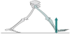
When the heel contacts the ground at initial contact, the foot begins to decelerate, and weight is taken onto the stance limb. During this period, the foot assumes a position of slight dorsiflexion. It does this by bending and internally rotating at the hip and knee to slow foot movement and the abrupt drop of body weight from forces arising at heel-strike [18,19]. The summary of bodily movements will consist of a slightly flexed hip and medially rotated; the knee is slightly extended; the tibia is laterally rotated; the ankle is at 90° with the foot supinated; and the hindfoot is everted [18,19,26]. As weight is taken onto the heel, the abrupt drop in body weight generates an immediate and transient GRF (Figure 7) between the foot and the ground. In order to maintain balance of the body as weight is taken onto the heel, rotation of the thorax occurs in the opposite direction of pelvic movement on the side of initial contact. The rotations at the pelvis provide counter-rotation forces between the swing and stance leg to decrease dips in the COG by lessening the angle of the femur with adjustments inlimb length [19,20]. As the trunk remains aligned between the two lower limbs [26], the GRF will be posterior to ankle and knee, and anterior to hip.
4.3 Motions at loading response period of gait
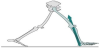
Load response follows the initial contact period of the foot’s contact with the ground; identified by a progressive foot-flat neutral posture of the foot during the gait cycle. During this period of normal gait, the body weight is transferred onto the stance limb, and the trunk aligns with the stance leg for stability [18,19]. The summary of bodily movements consists of advancing hip extension, the knee is slightly flexed, and the tibia begins to advance forward to move bodyweight over the fixed foot. As the body progresses over the foot, the ankle is plantar flexed, and the hind-foot inverts so the foot can move into a position of pronation [19]. This allows mobility and adaptation to different ground surfaces and postures of the body for effective shock absorption. Here, the forces will be slightly higher than body weight. The vGRF is aligned posterior to the ankle and knee, and anterior to the hip. See Figure 8.
4.4 Joint motions at mid stance period of gait
The Mid stance period is a period when full body weight is taken onto the stance limb. During this period of fixed foot support, the hip and knee has stopped rotating inwards and is now straight to contribute to the stability of the whole body for an upright standing position [18,19]. Additionally, COG is highest at mid stance. The summary of bodily movements consists of maximum extension and external rotation at the hip; the knee is locked in extension with the heel and forefoot in contact with the ground. During this period from liftoff of opposite leg to point where ankles of legs align in the frontal plane, the forefoot is pronated and hindfoot is inverted for even weight distribution across the entire foot [19]. The weight bearing capacity of the body as a whole is dependent on alignment of the three lower-extremity joints-hip, knee, and ankle. The vGRF vector is close to going through most joints, where it moves from behind the ankle joint axis to an anterior alignment of the ankle axis to balance and stabilize the gravitational effects acting on the body (Figure 9). During single-limb support, the vGRF will be less than body weight. Here, the downward acceleration of the COM and the upward inertial force act to reduce the GRF to 85% of body weight [18,22].
4.5 Joint motions at terminal stance period of gait
During the period of terminal stance, bodyweight moves forward on the foot so that only the big toe is in contact with the ground. In this instance of a heel off position, the stance extremity is unloading bodyweight to the contralateral limb to progress to the swing phase of gait [18,19]. As the trunk moves toward the supporting leg, the pelvis drops to the swing limb side but maintains a posteriorly rotated position to counter rotational forces between the swing and stance leg. The knee is in a position of extension, tibia externally rotated, ankle plantar flexed, and the heel assumes a neutral and slightly internally rotated position to drive movement of the body forward [19]. The continued advancement of the pelvis and lower extremity progress the tibia anteriorly to cause the heel to rise. Jointly, these actions help to smooth the pathway of the center of gravity. Here, the vGRF is located anterior to the ankle joint and progresses posterior to knee and hip joint to reverse the downward movement of the body (Figure 10). The vGRF will be higher than body weight at terminal stance associated to the combined push provided by the plantar flexors occurring through pre-swig.
4.6 Joint motions at pre-swing period of gait
The pre-swing phase is the toe off acceleration phase. From initial contact of the opposite leg to just prior to lift off, body weight is transferred to the swing leg as the toe pushes the leg forward to accelerate mass [19]. The trunk remains erect, the pelvis remains posteriorly rotated, and the hip is extended and slightly medially rotated. The knee flexes slightly, and the ankle is plantar flexed on the ground to generate momentum in order to push the leg forward and accelerate the hip forward in initial swing [18].
As shown in Figure 11, the GRF is located anterior to the ankle and posterior to the knee and hip joint during pre-swing. The active plantar flexors cause a second peak force greater than body weight as a result of the body's center of mass is being accelerated upwards to increase its upward velocity.
5. Materials and Methods
The material selection process used in this study is fashioned according to the Ashby’s procedure and consists of four steps, namely: translation, screening, ranking, and documentation [29]. Translation involves breaking down the design requirements into functions, constraints, objectives and free variables. In the screening step, nonnegotiable constraints are imposed on the materials and this result in the elimination of materials that cannot do the job. Ranking requires the use of material indices to indicate how well the screened materials perform the tasks based on specified properties. Finally, the documentation step investigates the materials selected in the ranking stage in order to choose the most compatible one. The details of the Screening and Ranking are similar to that reported in the previous study [5] and are provided below.
6. Results and Discussion
6.1 Translation
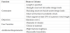
In this step, the requirements for an exoskeleton and prosthetic design are translated into basic models for proper analysis. The design requirements for an exoskeleton and prosthetic are given in the Function-Constraints-Objectives-Free Variables (FCOFV) chart of Table A-1 [5]. In addition to the preliminary FCOFV components, additional requirements such as high fracture toughness and reasonable formability were added in order for the material to accommodate the joint torques generated from ground reaction forces during walking.
6.2 Screening
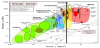
Screening consists of eliminating the materials that do not satisfy the basic needs; in this case the basic need is low density. Orthopedic and prosthetic devices available in the market are typically made out of Duralumin but Carbon Fiber Reinforced Polymer (CFRP), and steel (AISI 4130) have also been considered. The properties of Duralumin (Al-2024 T6), CFRP (longitudinal), and AISI 4130 steel are shown in Table B-1[30-34]. Duralumin is typically used for exoskeletons as it is well defined, already used in a variety of applications such as airplanes, and has a low density compared to that of steel and low cost compared to carbon fiber. The new material must be able to support up to 1.2 times the body weight as detailed in the section on the Kinetics of Walking. This suggests that the strength and stiffness properties of Duralumin may be an overkill in the current design of exoskeletons. The additional requirement for the material to absorb the joint torques generated from ground reaction forces during walking necessitate the evaluation the density, fracture toughness and formability of the material. With these parameters in mind, the strength versus density chart was plotted as shown in Figure A-1 to narrow down the suitable material classes [29]. Using Figure A-1 as a reference, it is clear that some metals, ceramics, composites, polymers and elastomers, natural materials, foams all meet the density requirement. In other words, these materials lie to the left of the vertical line which is situated at the density of Duralumin.
7. Ranking
All the materials that passed the screening step were then ranked, using material indices, based on how they fared when the constraints of weight, strength and cost, were applied. The exoskeleton and prosthetic devices were modeled using material indices for an inexpensive beam with prescribed strength, using Equation 1 [29].
In addition to an inexpensive beam with prescribed strength, the exoskeleton and prosthetic devices were also modeled as an inexpensive column with prescribed buckling load, as shown in Equation 2 [29].
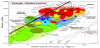
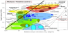
In these equations, M is the material indices, σy is the yield strength, Cm is the cost per kg, ρ is the materials density, and E is the Modulus of Elasticity. Figure A-2 addresses an inexpensive beam with prescribed strength [29]. By maximizing the material indices (Equation 1) in Figure A-2, represented by the bold line, the best material candidates are natural materials, and some metals and nontechnical ceramics. The materials are located above the bold line to the left of the chart. It is important to notice that this eliminates some of the materials found in the screening stage such as polymers and elastomers, foams, and composites (below the bold line). Figure A-3 addresses an inexpensive column with prescribed buckling load [29]. Maximizing the material indices in Equation 2, using the bold line, it is clear that natural materials, nontechnical ceramics, some technical ceramics, and some metals (above the bold line)) meet this requirement. Taking into account the material candidates from the screening stage as well as from Figures A-2 and A-3, the best material classes for this application is the natural materials, some metals, and some nontechnical ceramics. These set of materials are inexpensive and provide sufficient properties, based on the material indices, for the application.
8. Documentation: Assessment of Materials
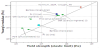
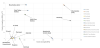
Having established that natural materials, nontechnical ceramics, and metals are best suited from the ranking step, it is therefore necessary to document these materials. There are a variety of natural materials, but the most commonly used in everyday application include fir, pine, oak, and bamboo. Figure 12 compares the Young’s modulus and yield strength for the natural materials stated above as well as Duralumin [5]. The bamboo considered in this plot is Moso Bamboo (phyllostachys edulis) as it is one of the most common, well defined, and strong bamboo species. Although nontechnical ceramics are not included in the plot, if they were, they would be located near bamboo. Figure 12 shows that besides Duralumin (Al- 2024 T6), Moso bamboo exhibits superior properties compared to the other natural materials. Figure 13 shows a density versus price graph for various materials including Fir, Pine, Oak, Moso bamboo, Duralumin, and Nontechnical Ceramics. The natural materials clearly show dominance in Figure 13 as they have the lowest density and cost. Although Moso bamboo is not as light as Fir, Pine, and Oak, it is the least expensive natural material discussed.
The mechanical properties of the various materials under consideration are shown in Table 2.
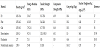
In Table 2, yellow represents the baseline which in this case is the Duralumin and green represents the properties superior in each category. When considering the application, it is very important to consider the compressive strength of materials especially in the case of muscle deficiency. More specifically, if a person lacks the muscle to absorb some of the reaction force, then the material being used must be able to withstand the entire reaction force not just the amount typically absorbed by the muscle. It has been found that during normal walking the vertical peak ground reaction force can reach 1.2 times the bodyweight in extreme cases [23]. The average body weight of a male is 80 kg which converts to about an 800 N force. In the case explained above, in which the extreme reaction force is 1.2 times the bodyweight, the reaction force would be 960 N. To withstand this reaction force, the cross-sectional area in which the force is applied was analyzed. Besides Duralumin, which is considered overkill, the Moso Bamboo requires the smallest area to accommodate the reaction force, as it has the largest compressive strength. Although the Duralumin meets the requirements in terms of materials properties, it is considered overkill because it’s density and cost are high in comparison with Moso Bamboo. This being said, the orthopedic device would not need to be bulky to sustain the forces of normal walking, as less surface area is needed.
8.1 Fracture toughness of materials
In addition to the Young’s modulus and yield strength, it is important to pay attention to the fracture toughness, as this is what dictates how much a material can take before a preexisting flaw causes failure. This property is very important because in many cases, such as single limb stance during normal walking, the device, if used for the supporting limb, must be able to support the balancing of the weight of the head, arms, and trunk. More specifically, devices such as the exoskeleton must be able to stabilize the lower extremity by using the external moments generated by the GRF to apply external moments at the knee and hip so the passive structures at these joints can provide support to keep the center of mass (COM) over the base of support. In order to maintain this stability, the material being used must possess high fracture toughness to avoid any flaw propagation which could cause the person to become unstable during normal walking [35,36]. Fracture toughness can be related to the yield strength, as shown in Equation 3, when considering the process zone, a plastic zone [30]. The process zone is generated by a stress concentration at the tip of the crack. For composites (natural materials being considered natural composites), the plastic zone is one of debonding, delamination, and fiber pull out [29].
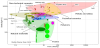
Figure 14 shows the fracture toughness versus yield strength for the natural materials, Duralumin (metal), and nontechnical ceramics.
Although Duralumin has a higher yield strength than bamboo, bamboo’s fracture toughness is higher. Compared to the other natural materials and nontechnical ceramics, bamboos fracture toughness and yield strength is far superior. The high fracture toughness of bamboos means that bamboo has a higher ability to resist fracture when a crack is present. Thus, if the ground reaction force (GRF) causes a crack in the exoskeleton, the amount of stress needed to propagate this crack is higher in bamboo compared to the other materials in Figure 14. Table 2 displays some properties of the four natural materials, nontechnical ceramics, as well as for Duralumin, which is considered the baseline as it is the current material used in exoskeletons. Natural materials are anisotropic and absorbent, thus their properties vary based on direction and moisture content, contributing to the variance in values shown in Table 2 [29-31,37-39].
8.2 Formability of materials
In addition to fracture toughness, it is important to consider the formability of each material. The material must possess reasonable formability as the construction of orthopedic devices, such as exoskeletons, require complex forming of various shapes. Formability is the ability of a material to undergo permanent deformation without being damaged. Nontechnical ceramics do not possess reasonable formability characteristics due to their brittle nature thus they were not considered. Bending natural materials into their desired shape is considered a measure of formability. Wei and company investigated the bending flexibility of Moso bamboo using two types of loading/ orientation, based on the arrow shape of the fibers [40]. These arrows shaped fibers point towards the inside of the bamboo culm [40]. The two loading types are when the arrow shape is pointing upwards (Type I) and pointing downwards (Type II) [40]. This study found that the notable bending characteristics of Moso bamboo is due to the “graded distribution and gradient variation of cell size of tougher fibers embedded in weaker parenchyma cells along the thickness of bamboo culm” [40].
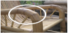
There are three main bending techniques used for natural materials: laminating, heating, and kerfing [41]. Laminating is the least laborintensive process involving gluing strips of natural material together [41]. Heating encompasses a variety of processes but the most common one being steam bending, in which the wood is put in a steam box to soften [41,42]. The heating process is the lengthiest process but produces flexible and stronger curves [41,42]. Kerfing, the last of the three bending processes, involves cutting a series of slits into the wood to allow bending [41]. Although kerfing is the quickest approach, it leaves the wood in a much weaker condition [41]. Bending with heat is the best method to form natural materials into their desired bent shape, as it does not weaken the material drastically and avoids altering the state of the material. Bending with heat is typically used on hardwood materials, such as bamboo and oak, as they possess high bending quality, whereas softwoods, such as fir and pine, possess low bending quality [43]. Oak can be bent with the steam bending process whereas bamboo is bent using a heat source such as a torch [44]. Figure 15 shows bamboo used in furniture after it has undergone the heat bending process [45].
Although all the natural materials investigated are capable of performing the required function while maintaining their rigidity, bamboo and oak are the only materials investigated with reasonable formability but bamboo is considered the best candidate for the exoskeleton and prosthetic application as its fracture toughness, strength, and cost exceed that of oak.
9. Assessment of some Indigenous Bamboos in the United States
There are over 1,000 species of bamboo and each of these species has their own set of properties. Within each species, their properties change based on many factors, some of which are moisture content, loading direction, state (culm, sectioned or fiber), age, and height.
The properties considered are based on the bamboo species in their culm state as well as axial measurement. Moisture content is one of the most common factors that affect the properties of bamboo and is assessed based on Equation 4 [46].
It is important to note that moisture content varies from top to bottom of the culm as well as throughout the thickness, with the inner wall having the highest moisture content [46]. The moisture content can range anywhere from 0-200% with the standard average moisture content being 12% [46]. The data shown in Table 3 shows how the physical and mechanical properties change based on the distance from the base and distance from the inside of the culm [38].
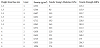
Although the data in Table 3 is said to be taken at a moisture content of 9.7%, it is important to note that this value is just an average. The reason for this is the moisture content is not homogenous throughout the culm as can be seen by the density value. The inner part of the culm is shown to have a higher density than the outer layer, due to its high moisture content. It can also be seen that the outer layer of the culm is the stiffest and strongest as its Young’s Modulus and Tensile Strength are higher. Additionally, the data taken from the samples further from the base (4 m) possess higher strength and stiffness properties than those taken closer to the base (1.3 m) due to their lower moisture content.
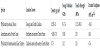
Table 4 contains the properties of well-known bamboo species, near standard moisture content, grown in the United States, where the primary exoskeleton and prosthetic market is [46-49].
10. Conclusion
It was previously found that bamboo is the best replacement for Duralumin for exoskeleton applications. Upon performing an extensive assessment, it was confirmed that bamboo is the best replacement as it is cheaper, lighter, has reasonable formability, and has superior fracture toughness properties to that of Duralumin, which appropriately satisfy the mechanical requirements needed to counteract the demands of the ground reaction force for the safe and effective transfers of body weight during stance limb loading. Additionally, bamboo’s suitability to preserve both sagittal and frontal plane kinematics for knee joint stability during single-limb stance was determined to be an important functional element for prosthetic exoskeleton design and its usage for basic orthopedic applications. Further investigation into the properties and dimensions of different bamboo species, available in the United States, indicated that each of these species were able to satisfy the exoskeleton and prosthetic material requirement as their strength properties exceeded the stress applied by the user.
Competing Interests
The authors declare that they have no competing interests.
Author Contributions
Talya Carnrike: Acquisition and data Analysis I and drafting the
manuscript.
Aruoture Egoh: Acquisition and data Analysis II and drafting the
manuscript.
Kischa S. Reed: Drafting and revising manuscript.
Peter N. Kalu: Drafting, revising manuscript and final approval for
manuscript to be sent out.