


1. Introduction
Functionally graded materials (FGMs) were firstly developed by a Japanese scientist in mid-1980s as structural components for using in severe thermal conditions [1]. The smooth variation of the effective material properties enables these materials to overcome the drawbacks of the conventional composite materials. Many investigations on the behaviour of FGM structures in the thermal environment have been reportedin the literature, contributions that are most relevant to the present work are briefly discussed below.
Employing the Rayleigh-Ritz method, Kim [2] studied the free vibration of a third-order shear deformable FGM plate in the thermal environment. The author has shown that the frequency of the plate is remarkably decreased by the temperature rise. Pradhan and Murmu [3] used the modified differential quadrature method in solving the equations of motion for free vibration of elastically foundation supported FGM sandwich beams in a high-temperature environment. Based on the higher-order shear deformation theory, Mahi et al. [4] derived an analytical solution for free vibration of FGM beams with temperature-dependent material properties. The improved thirdorder shear deformation theory was used by Wattanasakulpong et al. [5] to study the thermal buckling and free vibration of FGM beams. The authors concluded that the fundamental frequency of the beams approaches zero when the temperature raises towards the critical temperature. Ebrahimi et al. [6] employed the differential quadrature method to study the free vibration of FGM porous beams in the thermal environment. It has been shown by the authors that the fundamental frequency of the beams is significantly influenced by both the temperature and porosities.
The vibration of beams due to moving loads is often met in practice and isa subject of investigation for a long time. A large number of closed-form solutions for homogeneous beams subjected to different types of moving loads are presented in a well-known monograph by Frýba [7]. The dynamic analysis of FGM beams due to moving loads has been carried out by several researchers recently. Şimşek and Kocatürk [8] approximated the axial and transverse displacements by polynomials in their derivation of the equations of motion for an FGM Euler-Bernoulli beam under a moving harmonic load. Lagrange multiplier method was then employed in combination with Newmark method to compute the vibration characteristics of the beams. The method in [8] has been extended by Şimşek in studying the dynamic behavior of FGM beams under a moving mass [9], and a nonlinear FGM Timoshenko beam subjected to a moving harmonic load [10]. Khalili et al. [11] used the mix Ritz-differential quadrature method to compute the dynamic response of FGM Euler- Bernoulli beams carrying moving loads. The Runge-Kutta method was employed by Rajabi et al. [12] to investigate the dynamic behavior of an FGM Euler-Bernoulli beam under a moving oscillator. Nguyen et al. [13], Gan et al. [14] employed the finite element method to study the dynamic behavior of FGM beams traversed by moving forces.
To the authors' best knowledge, the dynamic behavior of FGM beams in the thermal environment due to a moving harmonic load has not been studied in the literature, and it will beconsidered in the present work. The material properties are considered to be dependent on the temperature, and they are graded in the thickness direction by a power-law distribution. The temperature is assumed to vary in the beam thickness only, and its distribution is obtained from the steady-state Fourier equation. Theequations of motion based onEuler- Bernoulli beam theory are derived from Hamilton's principle and they are solved by a finite element formulation in combination with the Newmark time-integration method. The effect of the material distribution, temperature change, and moving load parameters on the on the dynamic behavior of the beams is examined in detail and highlighted.
2. Functionally Graded Beam
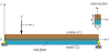
A simply supported FGM beam with rectangular cross section under a load F=F0cos(Ωt), moving from right to left, as shown in Figure 1is considered. Denoting the length, cross-sectional height and width of the beam as L, h and b, respectively. The x-axis is chosen to be on the mid-plane, and the z-axis is perpendicular to the mid-plane. The investigation is carried out based on thefollowing assumptions: (i) the load F is always in contact with the beam, and its velocity (v) is constant; (ii) the beam is initially at rest, and the inertial effect of the load F is negligible.
The beam material is formed fromceramic and metal with volume fraction of ceramic (Vc) and metal (Vm) is assumed to be given by
where n (0≤n<∞) is the grading index. In (1) and hereafter, the subscript “c” and “m” are used to indicate ceramic and metal, respectively.
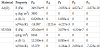
The beam material is considered to be dependent on the temperature, and a typical property (P) is a function of temperature (T) as [15]
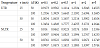
where T=T0 + ΔT, with T0 = 300 K is reference temperature and ΔT is the temperature rise, is the current environment temperature; P-1, P0, P1, P2 and P3 are coefficients of T and they are unique to the constituents. Table 1 lists the coefficients of Alumina (Al2O3) and Steel (SUS304), the constituents of the beam considered in this paper.
The effective material properties are evaluated by Voigt’s model read
From Eqs. (1) and (3), the effective Young’s modulus, thermal expansion and mass density are given by
where the mass density is considered to be independent of the temperature.
In the present work, the temperature is considered to vary in the thickness direction only, and itis assumed that the temperature being imposed to Tm at the bottom surface and Tc at the top surface. With this condition, the distribution of temperature in the thickness can be obtained as solution of the following Fourier equation (23)
where κ is the thermal conductivity, assumed to be independentof the temperature. The solution of Eq. (5) has the form (23)
If Tc= Tm, Eq. (6)gives a uniform temperature rise(UTR). Otherwise, it describes a nonlinear temperature rise (NLTR).
3. Governing equation
Based on the Euler-Bernoulli beam theory, the displacements u and w of an arbitrary point in the x and z directions, respectively are given by
where u0(x, t) and w0(x, t) are respectively the axial and transverse displacements of a point on the x-axis; t is the time, and (...), x denotes the derivative with respect to x. Based on linearly elastic behaviour, the normal strain (εx) and normal stress (σx) are as follows
The strain energy of the beam (UB) resulted from the mechanical loads reads
where A11, A12 and A22 are respectively the extensional, extensionalbending coupling and bending rigidities, defined as
With A is the cross-sectional area. With the effective Young’s modulus and temperature are given by Eqs. (4) and (6), the above rigidities can be evaluated.
The strain energy from initial stress due to the temperature rise (UT) is given by [4]
where NT is the axial force resultant caused by elevated temperature, defined as
with ΔT, as mentioned above, is the temperature rise. The kinetic energy of the beam (T) resulted from Eq. (7) is
where an overdot denotes the differentiation with respect to time, and I11, I12, I22 are the mass moments defined as
Finally, the potential of the moving forces (V) has a simple form as
with δ(.) is the delta Dirac function; x is the current position of load F with respect to the left end of the beam.
Applying Hamilton’s principle to Eqs. (9), (11), (13) and (15), we obtain the following equations of motion for the beam
The natural boundary conditions for the beam are as follows
where are respectively the prescribed axial, shear forces and moments at the beam ends.
The finite element method is employed herein for solving Eq. (16). To this end, the beam is assumed to be divided into some two-node elements with a length of l. The vector of nodal displacements (d) for a generic element has six components as
where u1, u2 are respectively the axial displacements at nodes 1 and 2; w1, θ1, w2, θ2 are the transverse displacements and rotations at the two nodes. In Eq. (18) and hereafter the superscript ‘T’ is used to denote a transpose of a vector or a matrix.
The axial displacement u and transverse displacement ware interpolated from the nodal values according to
where Hu= {Hu10 0 Hu20 0 }, Hw= {0 Hw1Hw20 Hw3Hw4} are the matrices of shape functions. Here, the following linear and cubic Hermite polynomials are used as the shape functions for u and w
and
Using the above shape functions, one can write the strain energy UB in the form
where kT is the element stiffness matrix due to the mechanical load with the following form
The strain energy resulted from the temperature rise can be written as
where kT is the stiffness matrix stemming from the temperature rise with the following form
Similarly, the kinetic energy can be written as
with the element consistent mass matrix m has the form
The finite element equation for undamped dynamic analysis of the beam has the form
where D, M and K are the total nodal displacement vector, mass and stiffness matrices, respectively; Fex is the total nodal load vector with the following form
The above nodal load vector contains all zero coefficients, except
for the element currently under loading. The notation
4. Results and Discussion
A computer code based on the developed formulation and described numerical algorithm is developed and employed to study the dynamic behavior of the beam in this Section. To this end, anFGM beam formed from Al2O3 and SUS304 with the materials data given in Table 1 under a moving harmonic load F=F0cos (Ωt) with F0=100 kN is considered here with. An aspect ratio L/h=20 is assumed, and a uniform increment time step, Δt=ΣT/500, where ΣT=L/v is the total time for the load F to cross the beam, are employed for computation reported below.
Validation of derived formulation is firstly confirmed by
comparing the numerical result of the present paper with the data
available in the literature. In Table 2, the frequency parameters,
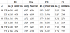
where is the maximum static deflection of the pure metal beam under a load F0. As seen from Table 3, the maximum DAF and the corresponding velocity of present work are in good agreement with that of Ref. [8]. It is worth to mention that the results in Table 2 and Table 3 are converged by using twenty elements, and this number of elements will be utilized for the all the numerical examples.
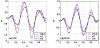
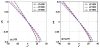
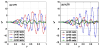
The effect of material distribution on the dynamic behavior of FGM beam in the thermal environment can be seen from Figure 2, where the time histories for the normalized deflection are illustrated for various values of the grading index n and v=20 m/s, Ω=15 rad/s, ΔT=50K. In the figure and hereafter, the traveling time and the mid-span deflection are normalized by the total time and the maximum static deflection, that is t*=t/ΣT and w*=w0(L/2,t)/w0st. As seen from Figure 2, at the given values of the moving load velocity, excitation frequency and temperature rise, the maximum mid-span deflection increases with the increase of the index n, regardless of the temperature type. The curves for the time histories obtained in the UTR are similar to that obtained in the NLTR, except for the higher amplitude.The increase of the mid-span deflection by raising the grading index n can also be seen from Figure 3 where the relation between the DAF and the index nis depicted for different temperature rises. The DAF steadily increase with the increase in the index n, irrespective of the temperature distribution. The DAF of the beam subjected to NLTR is smaller than that of the beam under UTR, but the relations between DAF and n of the two temperature distributions are very similar.
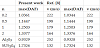
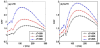
The influence of the temperature rise on the dynamic behavior of the FGM beam is illustrated in Figsure 4–6. The maximum mid-span deflection of the beam, as seen from Figure 4 increases by both the UTR and NLTR. The situation for the DAF, as can be observable from Figure 5, is similar, and the DAF increases with increasing the temperature rise. The influence of the UTR is more significant than that of the NLTR, and the DAF increases more significantly by the UTR. The curves exhibit the relation between the DAF and the moving load velocity have similar forms as that of a homogeneous beam subjected to a moving force [17], and the DAF experiences a repeated increase and decrease period before reaching a peak value, regardless of the temperature rise. The increase of the DAF by the temperature rise can also be seen from Table 4, where the DAF is given for various values of the moving load velocity, the temperature rise and the grading index n. Irrespective of the moving load velocity and the index n, the DAF in the table clearly increases by the temperature rise. The axial stress at the mid-span section, as seen from Fig. 6, also increases by the temperature rise, and the increase of the stress by UTR is more significant than by the NLTR. The stress in Figire 6 was calculated at the time when the load arrives at the mid-span and it was normalized by F0/A.
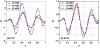
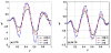
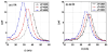
In Figure 7, the time histories for the normalized mid-span deflection are depicted for various values of the excitation frequency Ω and n=3, v=20 m/s, ΔT=50K. The effect of the excitation frequency on the dynamic behavior of the beam is clearly seen from the figure. The number of vibrations which the beam executes increase with increasing the excitation frequency. The vibration amplitude is much higher for the excitation frequency near the fundamental frequency, which equals to 34.4359 rad/s and 38.4791 rad/s for the UTR and NLTR of the figure, respectively. The influence of the excitation frequency on the dynamic behavior of the beam can be seen more clearly from Fig. 8, where the relation between DAF and the excitation frequency is illustrated for different temperature rises and n=3, v=20 m/s. The DAF rapidly increases when the excitation frequency approaches the fundamental frequency, irrespective of the temperature rise. Since the damping effect is ignored in the present work, the resonance will occur, and the DAF becomes infinity when the excitation frequency equals to the fundamental frequency. The excitation frequency at which the resonance can occur, as seen from Figure 8, changes with the temperature of the environment, and this should be taken into consideration in designing FGM beams subjected to moving harmonic loads. The resonant frequencies corresponding to the curves in Fig. 8 are 39.0262 rad/s, 34.4359 rad/s, 28.9872 rad/s for the UTR and 40.4788 rad/s, 38.4791 rad/s and 36.3454 rad/s for the NLTR.
5. Conclusion
The dynamic behavior of FGM beams in the thermal environment due to a moving harmonic load was investigated. The material properties are assumed to be temperature-dependentand they are graded in the thickness direction by the power-law distribution. Equations of motion derived from Hamilton’s principle and they are solved by a finite element formulation in combination with the Newmark method. The validation of the derived formulation has been confirmed by comparing the obtained numerical result with the data available in the literature. A parametric study was carried out on a beam with simply supported ends to highlight the influence of the material distribution, the temperature rise, the moving load velocity and excitation frequency on the dynamic behavior of the beam. The main conclusions of the paper can be summarized as follows.
- The dynamic characteristics of FGM beams under a moving load, including the mid-span dynamic deflection, DAF and axial stress are significantly influenced by the temperature, and they are increasedby the increase of the temperature rise. Among the two types of temperature distribution considered in the present work, the UTR has a stronger effect on the dynamic response than the NLTR does.
- The excitation frequency plays an important role in the dynamic behavior of the FGM beams due to moving harmonic load, and the resonance can occur when the excitation frequency and the fundamental frequency are identical. The resonant frequency, however changes with the change of the environment temperature, and this should be taken into account in designing the FGM beams in a thermal environment subjected to moving harmonic loads.
Competing Interests
The authors declare that they have no competing interests.