


1. Introduction
A suspension system is the most critical instrument to any vehicle’s harmony. It creates the coherence between road and driver, and synchronizes all components of a chassis that need to work together. Without it, the tempo would be thrown into unbalance between the driver and the road. A suspension system acts as intermediate between the axles of the vehicle and its frame.
The first job of any suspension is to support the frame of the vehicle and to maintain the proper geometrical relationship between the body and the wheels. The second mission of any suspension is to maximize the friction between the tires and the road surface and to act together with the tires to absorb and damp the various shocks and vibrations transmitted to the vehicle from the irregularities of the road in order to ensure the comfort of the passengers and to protect the safety of the cargo.
A suspension system usually consists of a spring, a shock absorber, a torsion barand linkages. The spring supports the static weight of the vehicle and transfers a part of it to the suspension component it rests on. When a car is subjected to shocks from the road surface, the springs act as a buffer: they compress and expand to absorb those shocks. However, because springs have the characteristics of continuing to oscillate, and because it often takes a long time for these oscillations to stop, riding comfort will be poor unless some means is provided to damp this oscillation and dissipate the energy from disturbances. This is the job of the damper (or shock absorber).
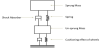
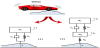
The total weight of all parts (body, engine, transmission, etc.) that come above the suspension and are supported by the springs is called the sprung weight. On the other hand, the weight of all parts (wheels, axles, etc.) which are not supported by the springs, constitute the unsprung weight. The figure 1 illustrates, in a line diagram model, the total suspension system for a vehicle.In order to control the movements of these two distinct weights, the springs and the shock absorbers should work in symbiosis, as in an inseparable unit.
Despite what is commonly imagined and what could suggest its name, it is not the damper, but rather, the spring that absorbs shocks. The stiffness of the springs controls the time response of the sprung mass while the car is being driven. A vehicle with a solid suspensionor no suspension minimize body motion well, but would transfer whatever forces the axles encounter, when running down the highway, directly to the frame and also to the passengers. Contrarily, when a suspension is too soft, such as in luxury cars,it can swallow bumps and provide a super-smooth ride; however, with such a suspension the vehicle is likely to bounce off the ground when the tires hit a bump. If the tires are off the ground, even for a fraction of a second, loss of control is possible. Springs of all types and shapes mounted on any vehicle’s suspension, appear as simple and ordinary mechanical components, but in reality they play a crucial role in the balance of passenger comfort and road handling.
When subjected to external disturbance the damper specific task is to slowdown and control the cyclic compression-rebound spring movements. In case a damper is missing or not efficient, many problems and dangerous phenomena could occur. As wheels would dance in an uncontrolled way on the road, they would not have adequate contact with the road, and it would thus become difficult to maintain the grip of the tire on the road, to use the brakes with efficiency, and even to preserve a trajectory.
Therefore, designing a good suspension must involve making a compromise between stability and comfort. This design contradiction cannot be solved using only passive elements [1]. So far, three types of suspension have been proposed and successfully implemented; passive, active, and semi active. The passive suspension system featuring oil damper provides design simplicity and cost-effectiveness. However, performance limitations are inevitable. On the other hand, the active suspension system provides high control performance in wide frequency range. But the active suspension requires high power sources, many sensors, servo-valves, and sophisticated control logic. One way to resolve these requirements of the active suspension system is to use the semi active suspension system. The semi active suspension system offers a desirable performance generally enhanced in the active mode without requiring large power sources and expensive hardware. During the past decade, very attractive and effective semi active suspension system featuring electro-rheological (ER) fluid has been proposed by many investigators [2,3].The ER damper is a devicefilled with a mixture of low viscosity oil and electric-field sensitive particles which deliver controllable damping force that can be applied to control vibration systems or semi-active suspension systems. Its response time is about few milliseconds [4]. A detail review of ER material advancement was presented by Symans and Constantinou [5].
For instance, in their studies, Petek [6] and Petek et al [7] manufactured prototype ER dampers and replaced conventional shock absorbers by the ER dampers. They investigated performance of the proposed ER dampers using sky-hook controller incorporated with the pitching, heaving, and rolling motion of the full-vehicle system. Weyenberg et al. [8] applied ER dampers to the semi-active suspension systems of vehicles controlled by a modified sky-hook algorithm, and directly installed accelerometers and position sensors in vehicles to measure the feedback signals of the vehicles. The results showed that the level of vehicle body acceleration and the tire load variation were improved.Wong et al. [9] and Wu et al. [10] used a parallel multi-electrode ER damper as well as various composite control strategies to improve both ride comfort and road holding. Nakano [11] constructed a quarter car suspension system model and proposed several semi-active control algorithms for ER damper, which showed that the proportional feedback control using the information of absolute un-sprung mass velocity is the most effective control strategy. Choi et al [12] manufactured an ER damper for a small-sized passenger vehicle and presented its control characteristics of the damping force. On the basis of this work, they extended their research and evaluated the control performance of the proposed ER damper using hardware-in-the-loop simulation [13]. Kuo et al designed and tested an electrorheological valve using serial multi-electrode [14]. From their experimental results, they found thatelectrorheological valve using serial multi-electrode has higher controllable characteristics than asingle-electrode ER valve. The electrorheological valve using serial multi-electrode is suitable forvehicle dampers that especially require short stroke and high damping force.Choi et al. [15] evaluated the performance characteristics of a semi-active ER suspension system associated with a skyhook controller and four ER shock absorbers to a full car. Their results showed that the semi-active system could be effectively employed in a passenger vehicle, improving both riding comfort and steering stability.
The purpose of this paper is to investigate the use of a new ER damper design for a possible intelligent semi active control of a vehicle suspension. Section 2 focuses on design and manufacturing details. Section 3 presents the characteristics of our ER fluid. In Section 4, the preparation and characterization of the ER fluid are detailed. In Section 5, the ER damper is applied to a single-degree-of-freedom (SDOF) model of a quarter-car suspension vibration systemto evaluate its dynamic response.
All technologies typically have mechanical issues, such as delamination problems, brittleness, fatigue and the like. Figure 4 show a phone cover made with Fused Deposition Modeling (FDM). After being dropped on the floor a number of times this cover started to break. This is less of a problem with SLS, however orientation of a part during build will influence on the mechanical properties also for this technology [11].
2. Design Details
2.1 Classic Bi-Tube Hydraulic Damper
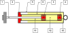
As explained in Figure 2, a conventional bi-tube hydraulic damper contains mainly two concentric metal cylindrical tubes. The external housing (5) protects the whole system from any hazardous chocks while the internal one (6) is serving as a piston chamber inside which a rod structure (1) secured to a piston (3) are axially free to move. The annular piston divides the chamber into two separate fluid chambers, an upper “rebound“ chamber [V1] and a lower “compression” chamber [V2]. The annular fluid transfer duct (4) provides fluid communication between inner and outer housings.
2.2 Modified ER Bi-Tube Hydraulic Damper
The schematic configuration and photograph of a modified ER bitube hydraulic damper proposed in a previous work [16] are shown in Figure 3. The ER effect is induced into the classic damper by adding a 40-milimeter tall annular cupper electrode, tightly fitted to the axially movable rod. The positive voltage produced by a high voltage supply unit“TREK Model 610D” is applied to the inner moving electrode, through an internal connection, while the negative voltage is connected to the damper metal cylindrical inner housing. There is a 1 mm gap between the two electrodes. In the absence of electric fields, the ER damper produces the damping force only by the fluid-flowing resistance. However, if a certain level of the electric voltage is supplied to the ER damper, the polarized particles instantaneously respond by aligning themselves along the field lines and additional damping force due to the yield stress of the ER fluid would be produced. This damping force of the ER damper can be continuously tuned by changing the voltage applied to the damper.

2.3 New design of a multi-electrode ER Damper
The results collected from laboratory tests and numerical simulation [16] of the above ER damper clearly show that damping characteristics could be drastically changed whenever one of the following three parameters is modified:
- The surface (the height) of the electrode;
- The electric field;
- The proportion of the dispersed particles.
However, any attempt to increase the mass percentage of particle would probably increase the chances of current short circuit and then an electric discharge due to the increase in the quantities of polarized particles in the same fluid volume and the building of more particle chains or bridges, which facilitates the migration of electrons from one electrode to the other. Moreover, attempting to excite the ER damper with an excessive voltage would not be possible because of the side effects of such an increase. Indeed, the oil leakage observed during all the tests, especially under strong electrical fields, was probably due to the yielding of the glue used to hold together the connecting wires and maintain the seal. High electrical field values are also undesired because of the disturbing effects they could induce on the electronics of the control systems. For all that reasons, the only remaining way to increase the damping would be by increasing the surface of the electrode.
Moreover, it can be noted that the design of an optimum suspension must make a compromise between stabilityand comfort. However, because such optimum depends on the excitation frequency, the designer should be aware of the limits of the mechanical design, which makes it impossible for an ER damper to be optimum over the entire range of frequencies. To take full advantage of the unique features of ER dampers, the controller used to control the damper, in response to measurements made by accelerometers, should not only apply an on/off policy, but should be able to vary the value of the high voltage.
According to the aforementioned remarks and as detailed in Figure 4, the new improved ER damper is mainly equipped with a sliding long-electrode (to insure high damping efficiency) but fragmented into four concentric cylindrical short-electrodes (to offer better command flexibility). All the four small electrodes are connected in parallel to allow the individual excitation/control of each one of them. This new design is different from the serial multi-electrode ER damper developed by other researchers [17].

The principal design parameters are: electrode length = 80 mm (4x20mm), electrode gap 1 mm, piston head diameter = 31.5 mm. The metal cylindrical outer housing has an external diameter of 45 mm and a thickness of 1.5 mm. The damper contains approximately 420 ml of ER fluid. The amount of fluid energized by the electric field at any given moment is approximately 8 cm3.
A special fasten extremity was designed to fix the upper damper part to the universal test machine.
3. Laboratory Facility and Experimental Setup
A mechanically-activated shaking table was specially designed to provide a laboratory facility for performing vibration control experiments. The load frame shown in Figure 5 was designed and built for the purpose of obtaining the ER damper response data necessary for identification studies.

In this setup, an eccentric actuator, coupled to a crank-rod system, was employed in order to drive the shake table holding the damper. A linear variable differential transformer (LVDT) was used to measure the displacement of the piston-rod of the ER damper, and a load cell with a range of 10kN was included in series with the damper to measure the output force. The data acquisition system employed consisted mainly of a computer and the “LABTECH RealtimeVISIONpro” software. Using this experimental setup, the response of the damper can be measured for a wide range of prescribed speeds.
4. The ER Fluid
4.1 Introduction
Most of the heterogeneous ERF cited in the literature or commercialized consist on polarized mineral or organic particles suspended in silicon oil. The silicon oil is particularly appreciated for its chemical and thermal stability, however its capacity to disperse and to maintain in suspension particles is not always satisfactory. Some other mineral oil may offer better results than silicone oil [17] and are lower cost. Recently mineral particles coated with organic products [19-23] have allowed obtaining remarkable ER properties. However for some applications (shock absorbers, brakes), molecules physically bonded may come away from the surface of particles as result of the high mechanical strain undergone by the ERF (repeated passage through diverse openings for shock absorbers so an important shear stress) In addition, these ERF do not present sufficient stability in time probably because there is no compatibility between particles and the dielectric oil. In the present work, we propose to use modified silica particles by chemically graft on their surface molecules having mesogens polarizables groups such for liquid crystals polymers (LCP). Grafting organic molecules on the silica has been carried by different methods [24,25]. In our case, PMHS was selected as interface between the silica and the polarizables molecules. This original grafting technique should increase ER response as well as the stability of the suspension since PMHS have a similar structure than silicone oil (dimethylsiloxane: DMS).
4.2 Experimental Procedure
4.2.1 Modification silica particles
The grafting is realized thanks to the reactivity of the silanols groups present on the surface of the silica. Fumed silica produced by fluka was used. This amorphous oxide has a primary particle size of 14nm, a surface area of 200 m2/g and a density of 2.3 g/cm3. Particles form branched, chain-like aggregates a few tenths of a micron long. Silica was activated by hydrochloric acid attack in order to increase the number of silanol. The powder is placed in 2M HCl acid solution under stirring at room temperature for 24 hours then filtered, washed with deionized water then dried during 24 hours at 60°C. The efficiency of activation was proved by infrared spectra obtained using KBr pellets on a Bruker optic FTIR spectrometer (EQUINOX 55). Measurements were automatically corrected for water and carbon dioxide. Figure 5 shows well that acid attack increases the number of active groupings by observing the broad band centred at 3430 cm-1 due to the OH stretch originating from silanol. We note that hydrochloric acid effect was higher than (HCl/HNO3 3:1) acid. PMHS is an oligomer containing Si-H groups that can react with silica silanol groups, as well as hydroxyl and allyl groups.
Then it is possible to use a part of the PMHS reactive hydrogen for reacting with silanol on silica surface while the rest of hydrogen will react with organic molecules containing hydroxyl and allyl groups. PMHS was then used as interface between silica and mesogens. In addition its similar structure with the dispersing DMS should improve suspension stability since with untreated silica, it was not possible to prepare an acceptable silica suspension in DMS with more than 5%wt. Polarizables molecules (PM) to be grafted on silica were prepared from the Dianhydro-D-glucitol (isosorbide: C6H10O4) and have the chemical structure given on Figure 6a. The grafting of PM on PMHS (Figure 6b) is made first, then PMHS is grafted to the surface of the silica (Figure 6c). PMHS and PM are diluted in the cyclohexane in proportion corresponding to 50 % grafting of Si-H. The mixture is heated to 60°C under stirring for 24 hours with H2PtCl6.6H2O as catalyst. FTIR analysis was used to notice that the grafting reaction was total through disappearance of the band at 1639 cm-1 relative to allyl. The mixture is then transferred in a Schlenk flask under inert atmosphere in the presence of the silica (Si/SiO2 = 8%wt) at room temperature for 4 hours. The modified silica is then filtered, washed several times in the cyclohexane and dried in 50°C during 48 h. Zeta potential measurements (Zeta Meter 3.0, Zeta-Meter, New York, NY) of initial silica and grafted silica suspensions (30mg/L) were performed.
On Figure 7 we can clearly observe the change of the surface state of silica. Initially, the surface charge of silica comes from the dissociation of the silanol groups depending on pH through the following process;
The activation of the silica increases the absolute value of the potential which explained by the increase of the number of the silanols groups. However, grafted silica has completely different superficial charge profile. In this case, surface charge is more governed by the hydrogen bonds due to oxygen on the grafted molecules. This explains the positive values of the potential for low pH compared to as received silica.
4.2.2 Preparation and characterization of the ERF
The ERF used in this work consists of particles of silica transplanted in suspension in the oil of silicone (47V100 from prolabo) with a dielectric constant of 2.46, density of 0.97, viscosity of 100 mPa.s at 25°C. The initial silica powder presents interesting rheological properties, however its stake in suspension in the silicon oil is very difficult. Indeed in percentages superior to 5 %wt, we begin to have an unusable frost(gel) for our applications. With the grafted silica, we reached 20 %wt without increasing too much the viscosity of the suspension. A good homogenization was obtained using an ultrasonic probe with a mechanical stirring. The stability of the obtained fluid was evaluated through a sedimentation test and allows to envisage a real use of this fluid. Rheological behaviour (shear stress-shear rate) of the ER suspensions was measured with a viscotester (Haake VT550) equipped with coaxial cylinders (Figure 9). The gap between the inner and the outer cylinder was 1 mm. The DC electric field was varied from 0 to 3 kV using a TREK 610D high voltage supplier.
5. Experimental Results
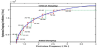
Filling the ER damper with the home-made homogeneous ER fluid (detailed here above), and using the set-up depicted in Figure 5, a wide range of piston linear speeds (ranging from 0.065 to 0.419 m/s) and voltage levels were considered and tested. In each test, the ER damper was driven with harmonic signals with different fixed frequencies, for specific displacement amplitude equal to 250mm, and the voltage applied to the prototype ER damper was held at a constant level. The electric field is set to a fixed value E = 1 kV/mm (U = 1kV) to avoid the electrodes dielectric breakdown and to avoid any disturbing interference with environing electronic devices. Figure 10 presents the measured damping characteristics as function of the number of excited electrodes. One can note that the damping force increased with the number of electrode, as expected before hand.
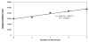
As the applied electric field increases, the damping force also increases due to the increment of yield stress of ER fluid under flow mode operation. However, the damping obtained by two electrodes is not being doubled when the number of electrodes is doubled (from 1 to 2 or from 2 to 4). As a matter of fact, the flow behavior of the ER fluid is influenced by not only the electrical field E (V/mm) and the coefficient of ER fluid material but also the inter-electrodes median gap, the fluid volume, the pressure drop created by the valve and other parameters related to the inherent damper design. For those reasons, the damping increase and the number of electrode increase are not following the same increase rate.
6. Numerical Simulation
To examine vibration isolation and road holding characteristics, an analysis can be performed using a simplified car model. The quartercar model is the basis for the suspension system’s design. Referring to Figure 11, the car suspension may be considered as a system with two-degree-of-freedom (where m1 and m2 represent the sprung mass and unsprung mass, respectively) or even a single degree of freedom (SDOF), a much simplified model that is mostly preferred because of its simplicity and that retains many of the essential characteristics of more complex systems in its response to excitation. In this simple idealized model, the spring for the suspension is assumed to be linear and the tire is also modeled as linear spring component.
The sprung mass m1 is supported by a spring ke (effective stiffness of the suspension spring and the tire stiffness, neglecting the wheel mass m2) in parallel with a viscous damper Ce. Thus:
and
If m2<< m1, the suspension system’s undamped natural frequency
is approximately
The movement equation of such a system is written in the following form:
where x(t) is the sprung mass displacement and y(t) is the wheel displacement commonly called base excitation.
When a car containing an ER damper is being driven over an undulating road at a velocity V, whose contour can be approximated fairly accurately by a sine wave having a wavelength L, the contour of the road acts as a support harmonic excitation on the system with an exciting frequency ω = 2πV/L. The base excitation input function will be of the form: y(t)= Y sin(ωt). The system response will be characterized by the Force Transmissibility TR, defined as the ratio of the transmitted force to the excitation force:
and the Amplification Ratio AR, defined as the ratio of the resulting to the excitation motion amplitude:
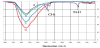
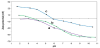
where r = ω/ωn is the frequency ratio. The way in which the transmissibility TR and the amplification ratio AR are influenced by the value of the damping constant C are represented in Figure 12. This figure is plotted for the particular case of a tourism car (weight around 1500 kg and natural frequency around 0.872 Hz) with a mass value m1 of about 375 Kg and a stiffness ke of about 25 kN/m.The excitation coming from the road is supposed to be around 1.5 Hz(ω/ωn = 1.72). The viscous damping Ce is derived from the experiment results as described in Figure 10 and depends on the velocity of the electrode as follows:
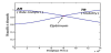
For a fixed excitation frequency of 1.5 Hz, the damping value was increased and the two parameters TR and AR are calculated and plotted as displayed in the Figure 12.
It can be noted that the damping constant of the damper determines both the stability of the vehicle and the comfort of travelers. A high damper (a damper with high damping characteristics) reduces the amplification and provides a good stability, keeping the tires in contact with the road and preventing frame oscillations and other problems, but it increases the force transmissibility and will transfer much of the road solicitation to the passenger, causing an uncomfortable ride. On the other hand, a soft damper (a damper with low damping characteristics) will increase ride comfort, but will equally reduce the stability of the vehicle. The design of a suspension is a compromise between stability and comfort, and an optimum level must be found.
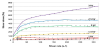
Since the two parameters TR and AR depend both on ζ(damping) and r(frequency), the location of the optimum point, defining the ideal compromise between comfort and stability as pinpointed in Figure 12, will be depending on the excitation frequency, as displayed in Figure 13. It appears that, with a constant damping value, it is impossible for a classical ER damper to be optimized over the entire range of frequencies. Therefore, in response to measurements made by accelerometers, the damper should not operate solely on an ON/ OFF basis to produce an ON/OFF ER damping, but should be able to deliver a varying damping value. Such variation could be either continuous or discrete. Because a continuous varying damping device is difficult and expensive to achieve, the innovative idea to use a fragmented long electrode could be an original approach to deliver a stepped (discrete) damping which values are depending on the number of excited electrodes.
……. stepped control with 4 electrodes;
- - - - Stepped control with 8 electrodes.
The continuous curve of Figure 13 could be approximated by another discrete one, which number of steps depends on the number of available electrodes. The more electrodes are available, the more both curves are close to each other.
7. Concluding Remarks
This paper proposes a new design of ER damper for the semiactive control of vehicle suspension system. A homogeneous organic/ inorganic ER fluid, where modified silica particles were dispersed in silicon oil, has been specially developed and incorporated into a damper prototype also specially used for this purpose. The new improved ER damper is mainly equipped with a sliding long-electrode (to insure high damping efficiency) but fragmented into four concentric cylindrical short-electrodes (to offer better command flexibility).
From the experiments and simulations carried out, it has been shown that the damping characteristics of the damper could be controlled through the variation of the applied voltage and the number of excited electrodes. In addition it has been shown firstly that the damping constant of the damper determines both the stability of the vehicle and the comfort of travelers and secondly that it is impossible for a classical ER damper to be optimized over the entire range of frequencies. Therefore, in response to measurements made by accelerometers, the damper should not operate exclusively on an ON/ OFF basis to produce an ON/OFF ER damping, but should be able to deliver also a varying damping value. Because a continuous varying damping device is difficult and expensive to achieve, the innovative idea to use a fragmented long electrode could be an original approach to deliver a stepped (discrete) damping which values are depending on the number of excited electrodes.
Competing Interests
The authors declare that they have no competing interests.
Acknowledgments
The authors would like to express their appreciation for the helpful comments and advice offered by the technical staff of the “SociétéInd ustrielled’Amortisseurs” and also for their active collaboration in the building and testing of this ER damper prototype.