


1. Introduction
Finite Element Analysis as a tool has existed for almost 50 years [1] , but due to the high number of equations the growth of this method has almost followed the growth in computer power. Under the NASA umbrella the program NASTRAN was developed in the 60’s and 70’s [2] , today there exist a large numbers of systems, very often linked to CAD programs like Solidworks, Inventor, CATIA etc. One of the big challenges has been to verify and validate the results from a simulation[3] , this article will not contribute to this discussion, however, the case studies are of course related to this topic. The user interface has become very easy and it’s quite easy to run an analysis on a structure designed in a CAD program. However, the simplicity in use does not imply that correct results are obtained.
In parallel with the evolution of FEA computer programs during the 1990s onwards we have seen the development of additive manufacturing. From its early start in 1988 [4], when the first SLA 3D printer was shown at the auto fair in Detroit, several technologies has emerged. In principle they are all similar in the sense they all produce parts layer by layer. The difference lies in the way these layers are produced and the type of materials available [5].
In this article the focus will be on powder-based versions of Additive Manufacturing (AM) equipment, popularly named 3D printing. The reason for this is that both case studies utilize this technology. The aim of this article, then, is to show a selection of best practice examples of the merger between Finite Element Analysis (FEA) and Additive Manufacturing (AM). This makes for further discussion on the challenges and possibilities that emerged through the two case studies.
2. Background
2.1 FEA, a short introduction
The theory for FEA was developed in the 1950s but the technology has evolved considerably over the last two decades. The general idea is to split an object into small elements virtually (Figure 1), set the boundary conditions and add forces, with loads and stresses calculated on every one of these generic shapes. The result may be displayed with vivid colors, depicting stress or displacements simultaneously for the whole model, where the elements works like pixels on a tv screen.
However, complex geometrical shapes needed a huge amount of elements, hence a need for a lot of computer power. Contrary to this, it is the complex shapes, those difficult to calculate using standard mechanical theory that is the real target [6] for FEA. This method of FEA could also be used to vary out the heat transfer analysis and the motion studies. One of the strong features of this tool is the level of communication. There is a huge step from presenting number to a 16 million-color palette mapped on the object being analyzed. Since this article is not about FEA as a method, readers are referred to further information may be found both online and in the published research and trade literature.
However, complex geometrical shapes needed a huge amount of elements, hence a need for a lot of computer power. Contrary to this, it is the complex shapes, those difficult to calculate using standard mechanical theory that is the real target. [6] for FEA. This method of FEA could also be used to vary out the heat transfer analysis and the motion studies. One of the strong features of this tool is the level of communication. There is a huge step from presenting number to a 16 million-color palette mapped on the object being analyzed. Since this article is not about FEA as a method, readers are referred to further information may be found both online and in the published research and trade literature.
2.2 Additive Manufacturing, popularly labeled 3D printing
All the different Additive Manufacturing Technologies (AMT hereafter) were developed over a few years at the end of the 1980s and at the start of the 1990s [4]. Today, almost 30 years later, the same technological principles still rule the business. However, it’s faster and improved in all possible ways. Further, the end of patents has led to the flurry of cheap 3D printers. This was also what started the hype [7] about 3D printing leading to the alleged next industrial revolution [8]. Five main principles have been delineated for 3D printing and AMT. There are five main principles for AMT[9] ; Stereo Lithography (SLA), Selective Laser Sintering (SLS), Fused Deposition Modelling (FDM), Laminated Object Modelling (LOM) and a more fuzzy class that could be labeled voxel printers. Both cases presented in this article are done with a powder-based method. Out of these five main principles for AMT, both cases presented in this article entail the powder based method.
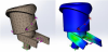
This method again could be divided in two; Selective Laser Sintering (SLS), invented by Carl Deckard [4] at University of Texas, and 3DPrinting (3DP), developed at MIT. The first, SLS, depicted in figure 2 is based on polymers, mainly Polyamide, with a temperature window for melting that is fairly defined. The process works in the way that a powder bed, the production area, are heated close to this temperature window and a laser scan the different layers, adding just enough energy to melt the PA powder, keeping any powder left or right of the beam still in powder form. New preheated powder is added to the build area between each layer. When the process is finished, and cooled down, the sintered polyamide parts are dug out of the part cake. This method gives strong, durable parts.
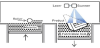
The other powder-based technology, developed by MIT, do not use heat, it is an ordinary inkjet plotter head that squirts out glue instead of ink as to make the different layers (Figure 3). In principle, the media printed could be anything powder based and gluable, though the most commonly used is plaster. This method was also the first to allow colors [9], adding them to the glue through the inkjet heads, again, very similar to color inkjet plotter. The advantage with this technology is rapidity, the possibility with colors and a high level of form freedom. The disadvantages, especially compared with SLS, are lower accuracy and low mechanical strength.
All technologies typically have mechanical issues, such as delamination problems, brittleness, fatigue and the like. Figure 4 show a phone cover made with Fused Deposition Modeling (FDM). After being dropped on the floor a number of times this cover started to break. This is less of a problem with SLS, however orientation of a part during build will influence on the mechanical properties also for this technology [11].

Initially, AM technologies were developed to produce fast and affordable prototypes through a product development process [12], hence the initial name, Rapid Prototyping. Still, one of the strong features of the technology is its functioning as a communicating tool, facilitating an enhanced understanding of product development, materials and printing technologies that may be developed and improved in teams [13]. Today, the idea of using AMT to produce end-user products is what makes the general public interested [14].
2.3 FEA and 3D printing
Since 3D printing has key features to produce complex geometry and non-uniform wall thickness, having a tool to analyze the mechanics of such products or structures is of course of great interest. However, due to mechanical issues in the 3D printing process, mentioned earlier, 3D printed parts are rarely used as critical mechanical components in a structure. One of the case studies will show this.
There is, however, work that uses FEA to enhance the understanding of how 3D printed materials mechanical properties are developed [15] ; By using simulation tools, the adhesiveness of each layer, by that the strength, based on the number of previous layers, could be estimated. There is also attempts to integrate simulation tools like FEA in the design process, an example of this is Finite Element Synthesis [16] that seek out to blend these two technologies during the design process, this will be further elaborated in the first case in section 3 below.
Initially, AM technology was developed to produce fast and affordable prototypes through a product development process [10], hence the initial name Rapid Prototyping. Still, one of the strong features of the technology is its functioning as a communicating tool, facilitating an enhanced understanding of product development, materials and printing technologies that may be developed and improved in teams [11]. Today, the idea of using AMT to produce end-user products is what makes interests the general public [12]. As seen in Figure 4.
Finally, there are attempts to use lightweight analysis tool to locate possible problem areas in an object meant to be 3D printed. Then through iterative steps it is possible to strengthen that specific area, for instance by adding material locally [17]. Yet, most of the combinations of the two technologies could be found as demonstrators of color mapping on 3D printed models. The following section presents two case studies where FEA and AMT are used in combination.
3. Two Case Studies
The following two case studies span over 10 years of investigations, both are performed at the Oslo School of Architecture and Design (AHO), though in collaboration with other institutions and companies. All the models presented were produced at AHO.
3.1 The open mesh tower
“The occasion was a manifestation and presentation of research activities from a large number of educational institutions and business companies in the Oslo area. The Oslo School of Architecture and Design was asked to provide a central, visual focus point for all the exhibitors and their pavilions and tents. Immediately, we saw our task as an opportunity, not merely to design and construct an object of visual interest, but to combine research and architectural design by trying out some new ideas”.[16] p; 2, Figure 5.

The result was a three-legged aluminium structure in the form of a twisted, triple helix featuring 67 joints with 25 variants. The idea was to explore structural form with a high level of geometrical complexity, in order to fully exploit the potential of Additive Manufacturing Technologies for variation and flexibility. If repetitiveness is no longer a premise for an economic design, what can be achieved architecturally by taking full use of contemporary layer by layer manufacturing technologies?
In a research context the sculpture is obviously not an aim but a means. It is by studying this object and how it can be made that we learn if and how AMT can offer a new way of making architectural and structural components. The idea of making a truss came from the observation that size matters greatly in these technologies, since the actual production equipment has a very limited scale. In relation with architecture, then, if we want to benefit from AM, one of the ways might well be in the form of making structural details. Hence, trying out the making of joints for a truss seemed like a good way of starting.
Architecturally, the idea was to bring in a new element, which complemented the classical orders of the empire buildings by architects Grosch/Schinkel dating from the 1830ties. As an antithesis to the severe tranquillity of the huge columns, we wanted to make a contrast which was livid, playful and geometrically more complex, as well as presenting very different materials; namely aluminium tubes and nylon joints. Hydro Aluminium at Raufoss manufactured the Aluminium tubes and the joints were produced with SLS technology at AHO. Before the actual production of the joints took place a structural study was performed. Using StaadPro, axial forces from dead load, wind load (10m/s) and from handling during assembly were calculated (Figure 6).

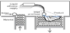
3D Systems white papers [18] claim a tension failure strength σf of 45 MPa, not saying anything about the direction. Based on the axial forces calculated in StaadPro, the joints with the largest loads were run through a FEA analysis using Cosmos. The results were very promising (Figure 7).
The layer-by-layer production method results in an anisotropic material, stronger in the x and y plane than in the z direction [11]. Delaminating could be a problem as the "arms" of the joint are pointing in all directions. Hence, some could turn out to be stronger than others.
The Technological Institute in Oslo was contacted to perform a number of tension and compression tests. Their equipment, however, could not handle samples larger than 25 millimetres in diameter, the actual structural joints being 35 millimetres. The test-joints had to be scaled down. All test samples were sintered vertically, whereby layers were oriented perpendicular to the direction of the force, this presumably being the weakest direction. The downscaled testjoints were glued to aluminium tubes (also scaled down to fitting proportions) (Figure 8).

The test results showed surprisingly low capacities. In about a third of the joints the glue failed and the aluminium tubes were pulled out, while in the rest of the joints we experienced failure of the joints themselves. Also, the failure load varied immensely, the lowest value resulting in a σf of 8 MPa.
When starting the construction some joints started to break, very often due to bending forces during assembling ( Figure 9a and Figure 9b). There were two types of fractures. Some joints fractured in the layer, typical delamination, while in others we observed more "standard" brittle fractures.

b. Brittle fracture in joint. Picture: Steinar Killi.
The calculations that were actually made for the whole structure indicated that even as low as 8 MPa would be sufficient as long as no heavy wind loads were applied.
When commencing the construction, some joints started to break. This was very often due to bending forces during assembling (see Figs 9a and b). This led to rethinking safety: the structure was meant to be in a public place, children might try to climb it, although it was never dimensioned for such use, nor were other safety issues anticipated. The project ended by being realized in AHO’s building facility, as the structure was deemed too dangerous to be placed in a public area (Figure 10 and Figure 11).


Although this case study is 10 years old now it clearly depicts challenges and possibilities seen today. The study in many ways does what was introduced in 2011 via the Finite Element Synthesis (FES) [16]. However, still today we would be hesitant to build this structure in a public place, as one weak joint could bring the whole structure down.
New research conducted by Zarbahksh et al [15] geared to understand and influence the mechanical properties in 3D printing could open some of the possibilities the open mesh tower demonstrates. An incredible freedom of creation may also be seen as load bearers, supported and conducted by FEA tools. These could be realized, not only in architecture but also in automotive industry and other areas of product design.
3.2 The pigeon tower
The second case study is closer to the origin of AMT;
It tackles prototypes as representations of the real product or structure. In this case a series of old, but amazing, buildings and constructions are closely scrutinized to understand how different functionality actually was achieved. This case study is just one of several constructions which may be viewed more thoroughly at www.sustainableenvironmentassociation.net .
This research group is international but strongly represented at the Oslo School of Architecture and Design. One of their main tasks, as written on their website is as follows:
“SEA pursues systematic, integrative and interdisciplinary research into the human-dominated and natural environment to explore their complex interlations. This is done with the aim to develop alternative approaches to architectural and urban design and sustainability.
SEA views the built environment as a vast repository of embedded
knowledge and approaches architectural history from a performance perspective.”
www.sustainableenvironmentassociation.net.
One of the buildings they have investigated is the pigeon tower (Figure 12) from Iran from around the first part of the 19th century [19] This structure, reaching up to 20 meter high, was meant to give shelter to wild pigeons, but also to collect manure as fertilizer. A tower like this could house up to 10 000 pigeons. A pigeon house could come in several variations, but usually as a drum-like structure, either hollow or an inner drum enclosed [19] . These houses were designed both to optimize space and access for pigeons, but also to provide climate shelter. People would typically enter the house once a year to collect the manure. Figure 13 shows a 3D printed model of the house.

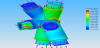
The study by SEA was to run climate and structural analysis of this building to obtain a better understanding of the architecture. By using FEA and AMT it became easier to interpret the results for the researchers, but also to disseminate the findings to a public in a manner most people would understand. Figure 14 shows temperature changes during the day, figure 15 show actual temperature mapped onto the model, printed out for three different times during the day. Finally, figure 16 shows a structural analysis of the dead weight of the 20-meter tall pigeon house in a cross-section.


Models and analysis by SEA.
To understand and to learn from prior, but in many ways ingenious older architecture is of great value in today’s pursuit for more sustainable living. The pigeon house is an example of a symbiosis between man and nature, which benefits them both. To lift this highly relevant, but often forgotten knowledge into today’s debate with stakeholders, politicians and policy makers - who cannot relate to calculations and complicated text - the pictures and models may function as key facilitators.
Regarding the technical outcome, and benefits from using models with FEA results mapped on, a number of key findings may be identified:
- The bridge between digital results on a screen to an actual printed model is now easy to cross, file formats are easily adapted for both technologies, and both technologies are available at a Figure 14: Temperature simulation through a day. Simulation by relatively low cost.
- Mapping FEA results on a 3D printed model utilize almost all the benefits in 3D printing; complexity, fast speed, cost effective, etc and none of the problems; few materials, mechanical issues, size etc.
- By working with representations of an object/structure both details and scale may be manipulated, for highlighting or as focal point to emphasize special features.
4. Discussion and Conclusion
When looking at the two cases it seems obvious that the latter one shows a merger between FEA and AMT that is operational today. The reason we do not see this more often may be explained by the number of companies and research groups/universities that possess both these technologies, preferably under the same roof. One could anticipate more cases with the blending of these two technologies, as representations, similar to what SEA has done. The communication output in multidisciplinary teams would benefit immensely from a conscious blending of FEA and AMT. In several respects the first case presented above mirrors problems that still prevail with 3D printing. These are issues to do with mechanical properties and repeatability. Research that could address these issues [13] and incorporate them with the possibility to customize any part of a structure [15] could unleash the potential in simulating and 3D printing of all kind of structures, and with a sufficient predictability.
Such a move to both simulating and printing, and the processes of moving dynamically between the two, may be understood as more than merely actions of merging elements of FEA and 3D printing. To date there are few formal, meta-level names for such relations in emerging characteristics of 3D-related technologies. We therefore give the name 3D Hydrogeny to this set of variable and complex relations between such tools and their application as design and not only engineering based resources for the further development of design and production processes in the wider domain of Additive manufacturing. The term 3D Hydrogeny is chosen to be deliberately generative in nature. It allows us to also extend the set of members of such a category to include a diversity of developments, some known and others still in progress and to be formulated in the future.
Competing Interests
The authors declare that they have no competing interests.
Acknowledgments
We are very grateful to SEA, Espen Bærheim, William Kempton and Maria Karlsen for contributing to this article