


1. Introduction
Friction stir welding (FSW), initially developed by The Welding Institute (TWI), has been widely used in welding of magnesium and aluminum alloys [1]. Recently, FSW has been identified as a potential technique for introduction of foreign ceramic particles into the stir zone of bulk alloys [2]. Since the main objective of this technique is to modify the microstructure of the alloy rather than to join, the technique has beentermed the friction stir process (FSP)[3,4]. FSP offers a low energy consumption route to introduce reinforcing ceramic phases into the metal matrix and to form bulk composites. One of the important parameters for successful FSP tool rotational speed, which contributes to the heat input generated during the process.
In recent years, several studies have produced metal matrix composites (MMCs) using FSP. For instance, Wang et al. [2] have produced bulk SiC-reinforced aluminum MMCs, and Lim et al. [5] have succeeded in developing multiwall carbon nanotube reinforced aluminum alloy composites while Ke et al. [6]have prepared in-situ Al-Ni intermetallic composites. Amorphous silica from rice huskash has shown good potentialfor replacing synthetic silica [7].This is especially true for the case where higher reactivity is required for Silica to give good bonding. Thus there is potential especially to use amorphous silica as reinforcement during FSP.
However, the method for incorporating the amorphous silica into aluminum bulk material still requires detailed investigation. This method is believed will overcome the shortcoming of conventional metal matrix composite fabrication process that typically occurs with direct mixing of reinforcement powder and metal powder either in solid state and liquid state processing including inhomogeneous distribution of reinforcement particles and porosity of the bulk composite[8-10].
Previous research [11] has indicated that tool rotational speed exerts a significant influence on the strength of FSWed and FSPed alloys and composites. While a number of researchers have reported efforts to produce aluminum matrix composite (AMC) using Al 1100 with conventional silica as reinforcement, none has reported the production of AMC using amorphous silica derived from rice husk-ash. Therefore, this work aims to investigate the microstructure and the wear behavior of the Al 1100 composite was fabricated using of amorphous silica obtained from silica rice husk as reinforcement particles by friction stirring process. Rotational speed of the stirring tool was varied in order to investigate the effectiveness of each speed in embedding of the silica powder in the aluminum matrix. The influence of different stirring tool rotational speeds, on the microstructure and mechanical properties of FSPed Al 1100 reinforced with silica particles was studiedin terms ofsilica powder dispersion and grain size as well as aluminum grain morphology.
2. Materials & Method
In this study, to produce amorphous silica powder, rice husk-ash was leached in acid and heated in a muffle furnace at a temperature of 500°C after soaking 3 hours. Then the silica powder was selectedto be deposited into a groove of 1 mm width and 0.5 mm depth machined on a 6-mm thick Al 1100 plate. Friction stir processing (FSP) was performed on two plates of Al100 with the groove below the rotating stirring tool. Based on the earlier research the parameters for FSP were selected [11-12]. The pin of the rotating stirring tool, made of high speed tool steel, had a diameter of 5mm and a length of 5 mm while the shoulder diameter was 20 mm.FSP was performed at600, 865, 1140 or 1500 rpm in aclockwise directionwith traverse speed of 45 mm/min and tool tilt angle of 2⁰.
Pin-On-Disc type testing machine (TR-20, DUCOM) with a counter surface disc made of hardened (62HRc) carbon steel EN-31. The wear test was performed in dry conditions at room temperature of ~25oC, at a fixed speed of 1 m/s and with various applied loads of 10 N, 30 N and 50 N. The wear pins with diameter of 12 mm transverse sections of the FSPed samples were cut for metallographic preparation prior to etchingwith hydrofluoric acid solution for 15 sec.
The distribution of the silica particles and microstructure of the FSPed Al100 plates were observed under both optical microscope and scanning electron microscope (SEM). Micro-hardness was measured using a micro-Vickers hardness tester with a load of 500 g for 10 s along different zones developed in the stir zone. Dry sliding wear test of the Al 1100 silica FSPed samples were performed by a pin-on-disc test machine with a 50N load and a slide speed of 0.5 mm/min for a distance of 500 m in order to measure the weight reduction and specific wear rate. The bonding between the matrix and silica particle was also observed using SEM.
3. Results and Discussion
3.1 Material flow in the stir zone
Figure 1 shows the cross sectional area of the alloy FSPed at different rotational speeds, revealing the typical material flow in the stir zone that is commonly found in the literature[13]. That is,the widest part is in the uppermost portion of the stir zone while the narrow part is at the lowest part of the pin which indirectly suggests the key role of the tool shoulder on the material stirring action. Alloy FSPed without addition of silica particles at a speed of 865 rpm (Figure 1a) shows thesmoother contour of the stir zone from the uppermostportions to the lowest portion than that of the alloyreinforced with silica particles FSPed at the same speed (Figure 1c). No defects in the form of cracksor porosities were detected in eithersample.The stir zone in alloy without silica particles was larger, covering about 50% of the cross-sectional area of the plate,which is greater than the area covered by the other alloys. This findingis attributable to the large heat input generatedin this alloy during FSP, which softened the base metal, enabling the soft aluminum to flow easily under the motion of the tool shoulder[14].

The material flow pattern in the alloy without silica particles (Figure 1a) was quite different fromthose containing silica particles,even when treated at the same rotationalspeed (Figure 1c).The alloy without silica particles showed both a non-smooth metal flow that resembled the shoulder and pin profile and sizes as well as the existence of a defect in the stir zone. The defect in the form of a cavity mainly originated in the joining line in the grooved area where the silica particles were deposited prior to FSP. Contrarily, the alloy with silica particles (Figure 1c) had a much smaller stir zone area, coveringonly about 30% of the plate cross-sectional area. This micrograph indicates that, although the same rotational speed was used, the tool was unable to penetrate deeper into the sample because the aluminum matrix is insufficiently soft owing to the presence of hard silica particlesin the aluminum, whichcreated resistance to the tool rotation during FSP. That is, the introduction of silica particles increased resistant to the tool, so the heat produced by the rotating pin was much lower than when the alloy was prepared without silica particles, thus thefriction heat was insufficient to soften the aluminum base material.
Lowering the rotational speed to 600 rpm was associated witha defect in the form of a cavityin the stir zone of the alloy prepared with silica, as shown in Figure 1(b). However, the flow pattern of the stir zone was similarto that shown by the alloy that also contained silica but which had been FSPed at 865rpm (Figure 1c). This behavior was also reported by Lee et al. [12], who have observed that the weld zone area decreased with decreasingrotational speed. This micrograph Figure 1balso indicated that the alloy had a non-smooth metal flow distribution during FSP, likely becauseinsufficient heat input was generatedduring the FSP owing to low friction heat in the slowly rotating tool. With the insufficient heat input, the material was hard and offered the high resistance to plastic deformation that prohibited the material to flow freelyin the stir zone.
As the rotating speed increased to 1140 rpm, the material flow was slightly improved, as indicated in Figure 3d, where no detected defects suggesting that the material flowed freely in the stir zone. The stir zones of the FSPed were much broader than those of the alloys presented in Figure 1b and c, which covered almost 45% of the total cross sectional area. This FSPed alloy exhibited a smooth metal flow without defect. The penetration of the tool was quite deep, indicating that the heat generated was sufficient to soften the base materials unlike in the case of the other FSPed alloys (Figure 1b and c).
In the alloy fabricated using a rotational speed of 1500 rpm, the stir zone became much broader, as it covered up to 50% of the plate total cross-sectional area, and no defect was detected. Lee et al. (2004) [15]have discussed similar findings during FSW of AZ91 Mg alloy/ SiC particle-reinforced composite where higher rotational speed and lower welding speed resulted inthe higher temperature and lower cooling rate in the weld zones that contributed to easy formation of plasticized metal in a wider range of the weld zone. The penetration of the toolat 1500 rpm (Figure 1e) was much deeper than that at 1140 rpm (Figure 1d)withthe stir zone almost reaching the bottom half of the sample. This depth of penetrationindicates that the base material became much softer, enabling the tool to penetrate deeper into the sample. In fact, the shape of the stir zone of thealloy processed at 1500 rpm was verysimilar to the shape of that of the non-reinforced alloy (Figure 1a).
The micrographs in Figure 1 suggest that the frictional heat generated by the shoulder was mainly responsible for the thickness of the stir zone. With the addition of hard ceramic amorphous silica particles that are non-conductive to heat, the amount of heat available to soften the aluminum matrix was low, resulting in limited metal flow under the shoulder, even underthe same rotational speed. Furthermore, as the frictional heat increased with increasing rotational speed, the heat transfer caused a temperature rise along with the thickness of the plate. The rotation of the shoulder on the top surface caused the temperature near the shoulder/plate interface to be higher than the temperature near the bottom region. Thus, the material near the top surface became softer and more easily stirred, which also has beensuggested by Lorrain et al. [16].
3.2 Microstructure of the stir zone
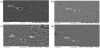
Optical images of the microstructures of the stir zone at higher magnification for Al 1100 both with and withoutaddition of amorphous silica particles are shown in Figure 2. Local variation inmicrostructures occurred because each stir zone received a different thermomechanical condition, as has also been observed by Murr et al. [17] during FSW of aluminum alloy.

Figure 2 shows thatthe stirred zone area appeared to havefine grains whose grain size was much smaller than that of the base metal. The average grain size was about 25μm compared to the base metal’s average of 50μm. This fine structure was produced by dynamic recrystallization and static grain growth after the stirring process, caused by the influence of frictional heat and plastic deformation. When no silica particles had beenintroduced, the average grain size (25μm) in the stirred zone was coarser than that of the sample with added silica particles (20μm). The alloy matrix grain size decreased slightly in the presence of silica particles, which may havelimited the extent of grain growth during FSP. The inhibition of metal grain boundary movement for grain growth by fine ceramic particles hasalsobeen proposed by Azizieh et al. [18].
It was observed that the average grain size of the aluminum matrix in the stirred zone decreased from 30μm to 10μm as rotational speed increased from 600 rpm to 1140 rpm. However, the average grain size of the aluminum matrix increased (25μm) as the rotational speed increased to 1500 rpm, as shown in Figure 2a-e. In the cross-sectional views in Figure 1a-d, the shape and size of the stirred zone under the shoulder for alloys with 600 rpm, 865 rpm and 1140 rpm can be seen not to have varied very much. This insignificant change suggests that with the increasing rotational speed, higher friction heat was produced by the rotating tool. At the same time the aluminum matrix under the shoulder area experienced more deformation leading to more significant dynamic re-crystallization. Since many finer nuclei formed during dynamic re-crystallization at higher temperature, grain growth was inhibited, leading to the finer grain in the stirred zone at 1140 rpm.
However, increasing the rotational speed to 1500 rpm was associated with a significant change in shape and size of the stirred zone. Although friction heat generated by 1500 rpm was the highest since it is the fastest speed of rotation, a temperature drop in the stirred zone could happen asmore of the aluminum matrix under the shoulder area was softened due to heat propagation. Consequently, thealuminum matrix in the stirred zone experienced less dynamic re-crystallization in comparison to that in the stirred zone in sample produced at 1140 rpm, leading to a coarser grain.
3.3 Material flow in the stir zone
Figure 3 shows that alloy FSPed at865 rpm without addition of SiO2 particles exhibited the lowest hardness value, about 45 Hv, in the stir zone area while that of the sample with addedamorphous silica particles showed a hardness of 99 Hv, although the tool rotational speed was the same. A more than 100% increment in hardness was achieved, then, with the introduction of silica particles in the stir zone. The introduction of silica particles disturbed the growth of the newly re-crystallized aluminum grains, resulting in finer grains in the composite. The composition of the silica particles in the stirred zone was about 30%, as shown in Figure 4b, and the average size of silica particles was observed to be 10μm. The addition of silica particles improved the hardness of the aluminum-silica composite surfaces to three times that of the base aluminum, as has also been reported by Kurt [19]and Mahmoud et al. [20].
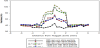
At the slowest tool rotational speed of 600 rpm, the peak hardness value was much lower (76 Hv) than that of alloy treated at 865 rpm (99 Hv). This low peak hardness value is mostly due to the low heat input introduced during FSPresulting from the low rotational speed which caused less aluminum base metal to besoftened so that less aluminum flowed during FSP. This explanation is supported by thelimited distribution of silica particles in the stirred zone area (Figure 4a). The silica particle compostion in the stirred zone area of the sample stirred at 600 rpm was about 15%. In addition, the silica particle size of the composited FSPed at 600 rpm was slightly coarse with an average particle size of 10μm in comparison to 9μm for the alloy FSPed at 865 rpm. It may be that the less efficient stirring action at the lowest rotational speed could not fracture the silica particles. At a rotational speed of 1140 rpm, the hardness values were much higher (108 Hv) than those of the alloy treated at 865 rpm (99 Hv). It has beendemonstrated by Kurt et al. [19]that the surface microhardness of the composites with added SiCp increases significantly with increasing rotational speed.
3.4 Wear properties
Results of the wear test in Figure 5 show that the weight of alloy without silica particles that was FSPed at a speed of 865 rpm reduced to 96.40% of its original weight after 500 m traveling distance. This value was quite significant (a 3.60% reduction) compared to alloy FSPedat the same speed but with addition ofamorphous silica particle reinforcement, this later alloy exhibited only a slight weight reduction (1.77%). At600 rpm, the FSPed composite had a weight reduction of 2.47%, which was lower than that of the alloy FSPed without silica reinforcement. Composites FSPed with a tool rotational speed of 1140 rpm showed a minimal amount of weight loss (1.36%) while the alloy FSPed at 1500 rpm showed a greater weight loss of 2.60%. This pattern of results of the wear test was in line with the hardness results of these composites.
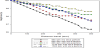
The specific wear rate (K’; Figure 6) for the alloy without silica particle reinforcement FSPed at 865 rpm was 3.24 × 10⁻⁶ mm³ N-¹ m-¹. As the units signify it is the volume of material removed per normal load per meter sliding distance.This value was higher thanthat of the alloy with silica particles at the same tool rotational speed, which had a specific wear rate of 1.47 × 10⁻⁶ mm³ N-¹ m-¹. This finding indicates that the addition of silica particles to Al 1100 could reduce significantly the specific wear rate. At 600 rpm speed was the lowest tool rotational speed studied, the specific wear rate for alloy with added amorphous silica was calculated to be 2.06 × 10⁻⁶ mm³ N-¹ m-¹. This specific wear ratewas much higher than that of thealloywith added amorphous silica FSPed at 865 rpm (1.47 × 10⁻⁶ mm³ N-¹ m-¹). However, at 1140 rpm tool rotational speed, the specific wear rate (1.18 × 10⁻⁶ mm³ N-¹ m-¹) was much lower than that ofthe other alloy with added amorphous silica. This low specific wear ratewas supported both by the good distribution of amorphous silica particles within the aluminum matrixand also due to a good bonding between the silicareinforcement and the aluminum matrix. Furthermore, the specific wear rate increased with the increase of rotational speed. At 1500 rpm rotational speed, the specific wear rate was calculated at 2.65 × 10⁻⁶ mm³ N-¹ m-¹. The increase in specific wear rate was due to the grain size factor, as discussed earlier. Rabinowics [21] has establish three types of adhesive wear condition – severe wear, moderate wear and mild wear –that are classified as ranges of K’ value ( ~10-² - 10-⁴, ~10-⁴ - 10-⁶, and ~10-⁶ - 10-⁸, respectively). Ourwear test resultsfor all the samples fell in wear condition categories of moderate and mild wear.

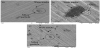
The drastic reduction inweight loss and the low specific wear rate could be attributed to the enhanced hardness of the aluminum alloy reinforced with silica particles, as notedby Ramesh et al. [22]. The SEM micrograph Figure 7a indicates that although the wear trackspassed through the silica particles, the silica particles seem to have stayedin their initial locations without being affected, i. e. withno deboning observed and wear debris accumulated behind the silica reinforcement particles (Figure 7b), showing that the silica particles strongly bonded with the alloy matrix. This scenario was observed in all the samples that had silica particles, where the silica were well distributed in the stirred zone area (Figure 7c). A significant reduction of direct contact load between aluminum in the surface ofFSPed composite and of wear test disk also contributed to the drastic reduction of weight loss, as also proposed by Mahmoud et al. [17].
4. Conclusion
Amorphous silica synthesized from rice husk was incorporated into 1100 aluminum alloys by friction stir processing. The effects of four tool rotational speeds were specifically evaluated. The microstructures and hardness of the stir zone processedat a tool rotational speed of 1140 rpm was found to be the optimum processing condition. At 1140 rpm, thefinest grain size and the highest hardness (105 Hv) were obtained in the silica-dispersed friction stir-processed zone. The hardness of the stirred zone in this samplewith amorphous silica particle reinforcement rose by almost 100% over that of the base metal alone.The wear test showed a significant reduction in the wear rate of the friction stir-processed zone with added amorphous silica particles. The SEM observation of the worn surface of the alloy with added amorphous silica particles showed no deboning between the particles and the matrix.
Competing Interests
The authors have no competing interests with the work presented in this manuscript.
Acknowledgments
The authors would like to acknowledge the School of Mechanical Engineering, USM, for allowing us to use their wear test facilities. Comments and advice from Alena L. Sanusi in improving the manuscript language and style are appreciated.