


1. Introduction
To overcome the inherently low corrosion and wear resistance of Mg-alloys, various surface coating methods and processes have been explored. A comprehensive review paper on this subject matter has been published by Gray [1]. Practically, most Mg-based components or products still require protective coatings to provide the necessary corrosion resistance and, in some cases, wear resistance. Indeed, over the years, much interest has been focused on the development of improved protective coatings for magnesium alloys with the aims of expanding the application range of Mg alloys as well as to meet the demands of the manufacturing industry. In this connection, laser cladding has been shown, by the authors [2-4] and other researchers [5- 8] to be an effective process for fabricating a relatively thick protective coating on Mg alloys that it can be an answer for improving the surface properties of the alloy. However, the inherent low melting and boiling temperatures, and the high chemical reactivity of Mg alloys, are issues that are difficult to be surmounted. Moreover, the severe dilution problem that often occurs in forming protective coatings on Mg alloys using laser cladding can results in a high Mg level in the coating and this can impair the resistance of the coating to corrosion. To circumvent the large difference between the low boiling point of Mg and the high melting point of most coating materials, this study employs a two-step approach, which firstly laser forms a composite layer containing the coating powder in an Mg substrate, and then uses laser cladding to form a continuous coating on top. Using such an approach, the coating powder needs not to be totally melted in the Mg molten pool in step 1; therefore a relatively low molten pool temperature can be afforded. This can minimise the dilution problem.
In this study, a high-entropy alloy (HEA) is used as the coating material. HEAs are a relatively new class of alloys proposed by Yeh [9, 10] they are designed based on the concept of multi-principal constituents, i.e. normally composed of more than five metallic elements in equi-atomic or close to equi-atomic ratios. Unlike most of the multi-elements alloys, HEAs exhibit only simple solid solution phases, basically fcc and/or bcc, they have a high degree of atomic disorder, and for some HEAs, nano-size precipitates are present. Their mechanical properties are comparable to those of metallic glasses. They are found to have excellent wear, corrosion and oxidation resistances [11]. Previous studies of HEAs have been mainly focussed in microstructural analysis and the evaluation of the properties of cast HEA materials; only a few studies used HEAs for surface modification and protection [12-15] and rarely on Mg substrates.
Indeed, over the past years, a lot of interest and great effort have been devoted to the search for a suitable laser surface treatment technique together with a suitable coating material with the prime objective of improving both the inherently poor corrosion and wear resistances of Mg and its alloys. The authors believed that given the unique characteristics of HEAs, i.e. composed of solid solution structures, together with their good mechanical and corrosion properties, it is anticipated that they will be capable of forming excellent protection coatings on Mg-alloys and in meeting the challenges for stress-bearing applications, in particular for the automotive and aircraft industries. This paper studies the phase development in the laser cladding of an AlCoCrCuFeNi HEA coating on an AZ91 Mg substrate. Since there is virtually no information available in the literature concerning the reactions between Mg and HEA materials in laser cladding, except those studies by the authors [15,16], the present study enables us to have a deeper understanding on the reactions between the HEA coating powder and Mg.
2. Experimental Details
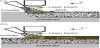
AlCoCrCuFeNi HEA (equi-atomic ratio) coatings were laser clad on AZ91 Mg alloy, which has a nominal composition of 9 wt-%Al, 1 wt-%Zn, and remainder Mg. In the experiment, gas-atomised HEA powder with a purity of 99.9 wt-% and a mesh size of 100-360 was used. Prior to the experiment, the powder was dehydrated using a vacuum oven. The cladding experiment was completed using a Rofin Sinar 5 kW CO2CW laser. A lateral powder feeder was used to transport the powder to the processing zone. Laser cladding was performed within a glove box filled with Ar gas. The laser light was guided into the box using a set of optical mirrors and through a window located at the top of the box. To prevent the HEA powder and the molten material from being oxidised during processing, dry argon was also used to deliver the powder to the molten pool. The laser beam of 2.8 mm diameter was used, the laser power was 1200 W, and the laser scanning velocity was 13 mm s-1. In the first attempt, complete melting of all the HEA powder in the melted pool of the substrate was not successfully achieved. This was due to the high liquidus temperature of the HEA (1603 K). when compared to the boiling point and melting point of Mg (1380K and 924K respectively), and the short processing time for laser cladding also limits the interaction time between the HEA powder and the molten Mg. To overcome this problem, previous studies have employed the pre-placed powder bed method [15], but this approach cannot be easily applied to surfaces with complex geometries. In this research work, a two-step powder feed cladding approach was adopted: first, the laser beam was used to produce a molten pool on the Mg substrate, and the HEA power was transferred to the pool with a direct blown powder method to produce a suspension of HEA powder in a Mg matrix (a composite layer) at the surface (Figure 1a). Subsequently, the surface of the specimen was ground and a second cladding step was performed on the specimen (Figure 1b). At this point, the laser light was mostly absorbed by the HEA powder at the surface and with additional powder being delivered to the surface, an HEA coating was formed.
Sections of the coating were prepared for microstructural characterisation. They were ground with emery paper down to 1200 grade and finished polished with 1 μm diamond paste. A scanning electron microscope (JEOL JSM-6490) equipped with an energy dispersive X-ray spectroscopy (EDS) facility was used to examine the microstructure of the unetched specimens. The phases of the coating were determined with an X-ray diffractometer (XRD) system from Rigaku SmartLab. The Padant software, based on the CALPHAD approach, was used to calculate the necessary phase diagrams for studying the microstructure development around the HEA powder.
3. Results and Discussion
3.1 Overall coating structure
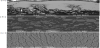
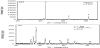
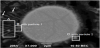
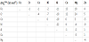
Figure 2a reveals that the two-step process resulted in an HEA coating being formed on the AZ91 substrate, with an intermediate layer of HEA particles in a matrix of AZ91 (Figure 2b). The XRD results of the top HEA coating and the intermediate layer (composite layer) are given in Figure 3a and Figure 3b, correspondingly. The XRD patterns show that the top layer of the coating was essentially comprised of a bcc solid solution phase, with no intermetallic phase detected. The top coating exhibits a fine dendritic structure (Figure 2c), which is typical for this type of HEA composition [17], while the XRD pattern of the composite layer indicates that it is composed mainly of α-Mg, γ-(Mg17Al12) and HEA powders (bcc phase) (Figure 3b). The XRD results suggest that the powders in the composite layer are surrounded by a hypoeutectic structure of AZ91. A closer examination of the layer revealed that reactions had occurred at the surfaces of the powders (Figure 4). However, an EDX analysis of an area close to the interface between the powder and the matrix (Fig. 4, location A) showed that with the exception of Cu, all other HEA elements did not appear to have markedly diffused into the matrix (Table 1). The slightly higher percentage of Al (12.11 at.-% is equal to 11.3 wt-%) than the nominal 9 wt-% of the AZ91 alloy was believed to be largely due to solidification segregation, with the possibility of a small amount of Al coming from the HEA powder. The following sections focus on examining the alloy dilution phenomenon from a thermodynamics standpoint and the reactions between the HEA powder and the AZ91 Mg matrix in the composite layer.

3.2 Alloy dilution
In the composite layer, a relatively high level of Cu was detected in the Mg matrix close to the HEA powder. This demonstrated that the HEA powder surface was dissolved in the course of laser cladding. Nevertheless, the intermixing of the HEA and the Mg matrix was not serious. In fact, it is crucial that the HEA mixing ratio was not significantly altered because a large departure from the original ratio may inhibit the HEA in forming simple solid solutions. The microstructure of the coated specimen also showed that the HEA powder did not fuse with the Mg matrix; but some Cu was rejected from the HEA alloy and entering into the molten AZ91 Mg. The lack of mixing can perhaps be explained in terms of the mixing enthalpy (ΔH) of the pairs of atoms between the HEA elements and the AZ91 Mg alloy. The comparatively high ΔH between (Fe, Cr, Co Ni) and Cu (Table 2) implies that Cu has a low tendency to be attracted by these elements, and as a result, Cu atoms are likely to be repulsed by these atoms during re-solidification and will therefore be rejected into the AZ91 Mg melt. On the other hand, even though a negative mixing enthalpy was obtained for the binary pairs of Ni-Mg and Al-Mg, the elements of Ni and Al have higher negative mixing enthalpies when pair with other HEA elements. Consequently, Ni and Al would have a tendency to stay within the HEA. Also, the relatively high ΔH between the HEA elements and Zn means that Zn is not strongly attracted to the HEA elements and will stay with the Mg alloy. As such, in the solidification of the AlCoCrCuFeNi alloy, Cu is the main element that would be highly likely to enter into the AZ91 substrate melt. Therefore, the AlCoCrFeNi composition can be perceived as the solvent, and Cu can be regarded as the solute. In the event that Cu accumulates at the liquid-solid interface of an HEA particle, reactions will occur. The following section discusses the possible solidification reactions at the HEA powder surface.
3.3 Reactions between HEA powder and matrix
The re-solidified surface of a HEA powder (Figure 4) showed that some faceted particles were formed. The EDX analysis results of the three locations shown in Figure 4 are presented in Table 1. Based on the lamellar morphology of the microstructure and the EDX results at location A, it is suggested that a eutectic structure of an Mg-Al-Cu ternary eutectic alloy was formed in the vicinity of the powder surface. The EDX analysis also showed that both locations B and C were Mg- Al-Cu rich. To further study the microstructure development around the HEA powder, the Padant software was employed to compute the phase diagrams of the Mg-Al-Cu system at 0.77 Mg, 0.51 Mg and 0.41Mg (molar fraction). These three compositions correspond to the EDX results at locations A, B and C; and the phase diagrams constructed are shown in Figure 5(a-c). The dotted vertical lines in these figures correspond to the chemical compositions of the EDX area analysis at locations A, B and C (Table 1), which are marked in Figure 4.
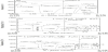
For location A, the phase diagram of Figure 5a suggests that a microstructure consisting of the Q+(Mg)+λ1 phases should be produced, and that the Q phase is formed through a peritectic reaction. However, the lamellar morphology of the microstructure shown in Figure 4. (location A), suggests that the eutectic phase should be formed by direct solidification from the melt and there is no evidence of a peritectic reaction. Moreover, at the tips of the eutectic growth (Figure 4, indicated by arrows), a trace of Zn was detected. This supports the supposition that a ternary Q+(Mg)+λ1 eutectic structure was formed by direct solidification of the melt and the presence of Zn was a result of element segregation during the solidification of the (Mg) phase. The deviation in not following a peritectic reaction, as predicted by the phase diagram, was likely due to a non-equilibrium eutectic reaction due to rapid solidification [19].
Turning to location B, according to the phase diagram of Figure 5b, the phase formation sequence of the alloy starts with the λ1 phase, and is followed by the eutectic solidification of Q+(Mg)+λ1. Moreover, according to the phase diagram, the faceted particle found within location B (Particle 1) would be the λ1 phase. The EDX analysis results of Particle 1 (Table 1), indicate that it is the λ1 phase, which has a chemical formula of (AlxCu1- x)2Mg (where x = 0.35). As is predicted from the phase diagram (Figure 5b), a eutectic phase will form; indeed, it was found that a eutectic structure was found growing from Particle 1. As for location C, according to Figure 5c, the solidification path of the alloy follows the sequence of λ1→L+Q→L+Q+T→Q+γ→T on cooling. The results of an XRD analysis of a faceted particle at location C (Particle 2 in Table 1) showed that it has a composition close to that of the T phase, i.e., (AlxCu1-x)49Mg32. With regard to Particle 2, i.e. the T phase, it is considered that it was formed through a peritectic reaction L+Q→T, in which the origin of the Q phase was from a non- equilibrium eutectic reaction. The EDX analysis also showed that the faceted phases of particles 1 and 2 contain some Co, Cr, Fe and Ni. In multi-component alloy structures, it is understood that Fe and Ni have a preference for the Al site, and although Ni can occupy the Al site, Co and Cr will settle on the Ni site.
4. Conclusion
In laser cladding of the AlCoCrCuFeNi HEA on Mg substrates, the problem of the great different in melting temperature between Mg and the HEA can be overcome by using a two-step cladding approach. The results of this study showed that a dense HEA layer of the AlCoCrCuFeNi composition can be obtained on top of a composite layer which consists of HEA powders in a matrix of α-Mg. In the composite layer, the HEA powders are partially melted upon resolidification, because Cu is less attracted to other HEA elements. As a result, AlCoCrCuFeNi composition can be obtained on top of a composite layer which consists of HEA powders in a matrix of α-Mg. In the composite layer, the HEA powders are partially melted upon re-solidification, because Cu is less attracted to other HEA elements. As a result, Cu is repelled and enters into the Mg melt and then solidifies, to a large degree, following the Mg-Al-Cu phase diagram, with the noticeable exception of the ternary Q+(Mg)+λ1 structure formed through a direct eutectic solidification and not the predicted peritectic reaction. This is considered to be due to rapid solidification. The merit of the two-step approach lies in the fact that the HEA powder is only slightly melted and no serious mixing in composition between the HEA and the Mg alloy occurs. This is imperative since a considerable deviation from the HEA composition would undermine the resistance of the AlCoCrCuFeNi coating to corrosion.
Competing Interests
The authors have no competing interests with the work presented in this manuscript.
Author Contributions
All the authors substantially contributed to the study conception and design as well as the acquisition and interpretation of the data and drafting the manuscript.