


1. Introduction
This section describes the different methods and techniques for providing energy for heating and cooling systems. It also, covers the optimisation and improvement of the operation conditions of the heat cycles and the performance of the ground source heat pump systems (GSHPs).
With the improvement of people’s living standards and the development of economies, heat pumps have become widely used for air conditioning. The driver to this was that environmental problems associated with the use of refrigeration equipment, the ozone layer depletion and global warming are increasingly becoming the main concerns in developed and developing countries alike. With development and enlargement of the cities in cold regions, the conventional heating methods can severely pollute the environment. In order to clean the cities, the governments drew many measures to restrict citizen heating by burning coal and oil and encourage them to use electric or gas-burning heating. New approaches are being studied and solar-assisted reversible absorption heat pump for small power applications using water-ammonia is under development [1].
An air-source heat pump is convenient to use and so it is a better method for electric heating. The ambient temperature in winter is comparatively high in most regions, so heat pumps with high efficiency can satisfy their heating requirement. On the other hand, a conventional heat pump is unable to meet the heating requirement in severely cold regions anyway, because its heating capacity decreases rapidly when ambient temperature is below -10oC. According to the weather data in cold regions, the air-source heat pump for heating applications must operate for long times with high efficiency and reliability when ambient temperature is as low as -15oC. Hence, much researches and developments have been conducted to enable heat pumps to operate steadily with high efficiency and reliability in low temperature environments [2]. For example, the burner of a room air conditioner, which uses kerosene, was developed to improve the performance in low outside temperature [3]. Similarly, the packaged heat pump with variable frequency scroll compressor was developed to realise high temperature air supply and high capacity even under the low ambient temperature of -10 to -20oC [4]. Such a heat pump systems can be conveniently used for heating in cold regions. However, the importance of targeting the low capacity range is clear if one has in mind that the air conditioning units below 10 kW cooling account for more than 90% of the total number of units installed in the EU [5].
Conventional heating or cooling systems require energy from limited resources, e.g., electricity and natural gas, which have become increasingly more expensive and are at times subjects to shortages. Much attention has been given to sources subject to sources of energy that exist as natural phenomena. Such energy includes geothermal energy, solar energy, tidal energy, and wind generated energy. While all of these energy sources have advantages and disadvantages, geothermal energy, i.e., energy derived from the earth or ground, has been considered by many as the most reliable, readily available, and most easily tapped of the natural phenomena.
Ground source based geothermal systems have been used with heat pumps or air handling units to satisfy building HVAC (heating, ventilation, and air conditioning) loads. These systems are favoured because geothermal systems are environmentally friendly and have low greenhouse emissions.
The installation and operation of a geothermal system of the present invention may be affected by various factors. These factors include, but are not limited to, the field size, the hydrology of the site the thermal conductivity and thermal diffusivity of the rock formation, the number of wells, the distribution pattern of the wells, the drilled depth of each well, and the building load profiles. Undersized field installations require higher duty cycles, which may result in more extreme water temperatures and lower HVAC performance in certain cases. Oversized field designs, on the other hand, require more wells, pumps and field plumbing and therefore will be more expensive, albeit adequate to handle almost any load circumstances. The detailed knowledge of the field rock (e.g., porosity, permeability, thermal diffusivity, heat capacity, or other aquifer parameters) may facilitate the determination of the appropriate drilling depth for each well, as well as the number and position of such wells needed at that site. Some of this information may be obtained during the drilling operation.
2. Earth-Eneargy Systems(EESs)
The earth-energy systems, EESs, have two parts; a circuit of underground piping outside the house, and a heat pump unit inside the house. And unlike the air-source heat pump, where one heat exchanger (and frequently the compressor) is located outside, the entire GSHP unit for the EES is located inside the house.
The outdoor piping system can be either an open system or closed loop. An open system takes advantage of the heat retained in an underground body of water. The water is drawn up through a well directly to the heat exchanger, where its heat is extracted. The water is discharged either to an aboveground body of water, such as a stream or pond, or back to the underground water body through a separate well. Closed-loop systems, on the other hand, collect heat from the ground by means of a continuous loop of piping buried underground. An antifreeze solution (or refrigerant in the case of a direct expansion ‘DX’ earth-energy system), which has been chilled by the heat pump's refrigeration system to several degrees colder than the outside soil, circulates through the piping, absorbing heat from the surrounding soil.
In some EESs, a heat exchanger, sometimes called a "desuperheater", takes heat from the hot refrigerant after it leaves the compressor. Water from the home's water heater is pumped through a coil ahead of the condenser coil, in order that some of the heat that would have been dissipated at the condenser is used to heat water. Excess heat is always available in the cooling mode, and is also available in the heating mode during mild weather when the heat pump is above the balance point and not working to full capacity. Other EESs heat domestic hot water (DHW) on demand: the whole machine switches to heating DHW when it is required.
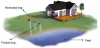
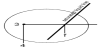
Hot water heating is easy with EESs because the compressor is located inside. Because EESs have relatively constant heating capacity, they generally have many more hours of surplus heating capacity than required for space heating. In fact, there are sources of energy all around in the form of stored solar energy, which even if they have a low temperature, can provide the surroundings with enough energy to heat the soil, bedrock and ground water as a heat source for domestic dwellings as shown in Figure 1, for example. Some emphasis has recently been put on the utilisation of the ambient energy from ground source and other renewable energy sources in order to stimulate alternative energy sources for heating and cooling of buildings. Exploitation of renewable energy sources and particularly ground heat in buildings can significantly contribute towards reducing dependency on fossil fuels.
2.1 The cooling cycle
The cooling cycle is basically the reverse of the heating cycle. The reversing valve changes the direction of the refrigerant flow. The refrigerant picks up heat from the house air and transfers it directly in DX systems or to the ground water or antifreeze mixture. The heat is then pumped outside, into a water body or return well (in the case of an open system), or into the underground piping (in the case of a closed-loop system). Once again, some of this excess heat can be used to preheat domestic hot water.
Unlike air-source heat pumps, EESs do not require a defrost cycle. Underground temperatures are much more stable than air temperature, and the heat pump unit itself is located inside; therefore, problems with frost do not arise.
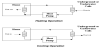
2.2 Function of the GSHP circuit
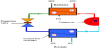
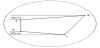
The collector liquid (cooling medium) is pumped up from the borehole in tubing and passed to the heat pump. Another fluid, a refrigerant, circulates in the heat pump in a closed system with the most important characteristic of having a low boiling point. When the refrigerant reaches the evaporator, which has received energy from the borehole, and the refrigerant evaporates. The vapour is fed to a compressor where it is compressed. This results in a high increase in temperature. The warm refrigerant is fed to the condenser, which is positioned in the boiler water. Here the refrigerant gives off its energy to the boiler water, so that its temperature drops and the refrigerant changes state from gas to liquid. The refrigerant then goes via filters to an expansion valve, where the pressure and temperature are further reduced. The refrigerant has now completed its circuit and is once more fed into the evaporator where it is evaporated yet again due to the effect of the energy that the collector has carried from the energy source (Figure 2).
Efficiencies of the GSHP systems are much greater than conventional air-source heat pump systems. A higher COP (coefficient of performance) can be achieved by a GSHP because the source/sink earth temperature is relatively constant compared to air temperatures. Additionally, heat is absorbed and rejected through water, which is a more desirable heat transfer medium because of its relatively high heat capacity. The GSHP systems rely on the fact that, under normal geothermal gradients of about 0.5oF/100 ft (30oC/km), the earth temperature is roughly constant in a zone extending from about 20 ft (6.1 m) deep to about 150 ft (45.7 m) deep. This constant temperature interval within the earth is the result of a complex interaction of heat fluxes from above (the sun and the atmosphere) and from below (the earth interior). As a result, the temperature of this interval within the earth is approximately equal to the average annual air temperature [6]. Above this zone (less than about 20 feet (6.1 m) deep), the earth temperature is a damped version of the air temperature at the earth’s surface. Below this zone (greater than about 150 ft (45.7 m) deep), the earth temperature begins to rise according to the natural geothermal gradient. The storage concept is based on a modular design that will facilitate active control and optimisation of thermal input/output, and it can be adapted for simultaneous heating and cooling often needed in large service and institutional buildings [7]. Loading of the core is done by diverting warm and cold air from the heat pump through the core during periods with excess capacity compared to the current need of the building [8-10]. The cool section of the core can also be loaded directly with air during the night, especially in spring and fall when nights are cold and days may be warm.
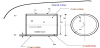
2.3 Free Cooling
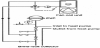
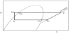
The installation can additionally be fitted with fan convectors, for example, in order to allow connections for free cooling (Figure 3). To avoid condensation, pipes and other cold surfaces must be insulated with diffusion proof material. Where the cooling demand is high, fan convectors with drip tray and drain connection are needed.
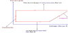
2.4 Refrigeration and Heat Pumps
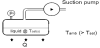
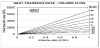
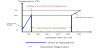
The pressure (ps) is a function of how rapidly vapour can be removed through suction or formed through pressure. At equilibrium, the rate at which vapour is formed (determined by Q) equals the rate at which it is removed. Therefore, both the heat transfer rate into the liquid (Q) and the vapour removal rate (suction pump capacity) determines the pressure and hence Tsat(s) (Figure 4). This is governed by the following set of equations.
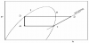
Both hfg and vg depend on the saturation temperature (or pressure) as assumed in Figure 5, which describes the relationship represented by eqn. 4.
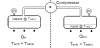
The RHS of the Figure 6 is the 'converse' of the LHS, and constitutes a heat pump. Heat is 'pumped' from the LHS to the RHS. The main difference is that the vapour, after compression, will almost certainly be superheated and must cool to Tsat(c) before condensing will occur. The same reasoning (in converse) applies to the RHS as previously applied to LHS. Obviously, with the above system, the entire refrigerant would eventually end up on the RHS, and the heat pumping (& refrigeration) effect would cease.
Clearly, to ensure that the system can operate continuously liquid refrigerant needs to be fed from the RHS back to the LHS. This can be achieved by simply allowing it to flow back under its natural pressure difference. In this way a continuous closed circuit refrigeration (Or heat pump) system is obtained (Figure 7).
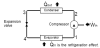
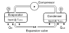
Control of the liquid flow rate is needed to ensure that it equals the vapour formation rate, and an appropriate balance of liquid quantities in the evaporator and condenser is maintained. When the liquid passes through the expansion valve it experiences a sudden drop in pressure, which causes instantaneous boiling (known as flashing). Vapour is formed using the liquid's sensible heat, which causes the liquid to drop in temperature to Tsat(s). A saturated liquid/vapour mixture will enter the evaporator. Figure 8 explains this cycle in practice.
2.5 System Performance
The system balance requires the overall work done to be equivalent to the net energy used by the system. Hence,
For operation as a refrigerator, a measure of system performance is the amount of heat absorbed per unit work supplied to drive the system. This is known as the Coefficient of Performance [11].
For operation as a heat pump, a measure of system performance is the amount of heat delivered per unit work supplied to drive the system. This is known as the Coefficient of Performance [12].
It follows that (for the same system):
2.6 Vapour Compression Refrigeration
The term “vapour compression refrigeration” is somewhat of a misnomer, it would be more accurately described as 'vapour suction refrigeration'. Vapour compression is used to reclaim the refrigerant and is more aptly applied to heat pumps. Vapour compression refrigeration exploits the fact that the boiling temperature of a liquid is intimately tied to its pressure. Generally, when the pressure on a liquid is raised its boiling (and condensing) temperature rises, and vice-versa. This is known as the saturation pressure-temperature relationship.
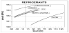
2.7 Refrigerant properties
In practice, the choice of a refrigerant is a compromise, e.g., Ammonia is good but toxic and flammable while R12 is very good but detrimental to the Ozone layer. Figure 9 shows some commonly used refrigerants and their typical ranges of usability.
Ideally, a refrigerant will have the following characteristics.
- Non-toxic - for health and safety reasons.
- Non-flammable - to avoid risks of fire or explosion.
- Operate at modest positive pressures - to minimise pipe and component weights (for strength) and avoid air leakage into the system.
- Have a high vapour density – to keep the compressor capacity to a minimum and pipe diameters relatively small.
- Easily transportable - because refrigerants are normally gases at SSL conditions they are stored in pressurised containers.
- Environmentally friendly - non-polluting & non-detrimental to the atmosphere, water or ground.
- Easily re-cycleable, and relatively inexpensive to produce.
- Compatible with the materials of the refrigeration system - noncorrosive, miscible with oil, and chemically benign.
2.8 Cooling Mode
In the cooling mode, cool vapour arrives at the compressor after absorbing heat from the air in the building. The compressor compresses the cool vapour into a smaller volume, increasing its heat density. The refrigerant exits the compressor as a hot vapour, which then goes into the earth loop field. The loops act as a condenser condensing the vapour until it is virtually all liquid. The refrigerant leaves the earth loops as a warm liquid. The flow control regulates the flow from the condenser such that only liquid refrigerant passes through the control. The refrigerant expands as it exits the flow control unit and becomes a cold liquid.
2.9 Heat pump antifreeze
A potential negative effect of all geothermal heat pumps is the release of antifreeze solutions to the environment. Antifreeze solutions are required in colder climates to prevent the circulating fluid from freezing. Antifreeze chemicals include methanol, ethanol, potassium acetate, propylene glycol, calcium magnesium acetate (CMA), and urea. These chemicals are generally mixed with water when used as a heat exchange fluid. These chemicals can be released to the environment via spills or corrosion of system components. Approved antifreezes include methanol, ethanol, propylene glycol, calcium chloride, or ethylene glycol. These antifreezes must be mixed with water, at concentrations of 20% or less. Geothermal heat pumps for a single-family residence and the antifreezes for these units were evaluated by Heinonen et al., (1996) [13]. These authors evaluated total energy consumption, corrosion due to the antifreeze, and the operational and environmental effects of six antifreeze solutions, namely methanol, ethanol, potassium acetate, propylene glycol, CMA, and urea. However, the excluded salt solutions, such as sodium and calcium chloride, from their study because they pose serious potential corrosion problems. The differences in total energy consumption for the studied antifreezes were considered minimal. Nevertheless, Heinonen et al., recommended that propylene glycol was a good choice based on its low health, fire, and environmental risks (Table 1). Unfortunately, these authors did not assess the leak potential of these antifreezes in the plastic pipe (e.g., HDPE & CPVC SDR-11) commonly used for the ground loop [14].

However, the bond between the grout and borehole can be compromised by desiccation of the geologic materials near the borehole, as the heat from the borehole lowers the moisture content of the geologic materials and these materials contract. In areas with thick unsaturated zones, the bentonite grout may dry out over time, compromising the seal. To improve heat exchange, some advocate the use of spacers, which moves the heat conductor pipe to the side of the borehole, putting it in contact with the geologic materials. However, the use of spacers appears to increase the environmental risk of antifreeze leaking into groundwater, by reducing or removing the bentonite between the heat conductor pipe and geologic materials.
3. Air Distribution
The air distribution system can make a big difference in both the cost and the effectiveness of geothermal heating and cooling. It also has an important effect on personal comfort and health. The airhandling component is either a separate cabinet or is part of the cabinet that houses the geothermal heat pump, and includes the blower assembly that forces air through the ductwork. The supply ductwork carries air from the air handles to the rooms. Typically, each room has at least one supply duct and larger rooms may have several. The return ductwork moves air from the room back to the air handler. Most buildings have one or more main return ducts located in a central area. The cold liquid refrigerant is circulated through the air handler where it absorbs and removes the unwanted heat from the air and vaporises the refrigerant to a gas. The gas is compressed to increase its temperature and then the underground/underwater coils act as a condenser rather than an evaporator (as in the heating cycle) (Figure 10). The heat in the refrigerant is transferred to the ground/ water as the refrigerant condenses.
Refrigerants are present in the GSHP systems and so present the threat of the HCFCs and toxicity. However, new types and blends of refrigerant (some using CO2) with minimal negative impacts are approaching the market as shown in Table 2. Because the GSHPs raise the temperature to around 40°C they are most suitable for underfloor heating systems or low-temperature radiators, which require temperatures of between 30° and 35°C. Higher outputs, such as to conventional radiators requiring higher temperatures of around 60° to 80°C can be obtained through use of the GSHP in combination with a conventional boiler or immersion heater.

The GSHPs come in 15 models from 4 kW up to 30 kW (even up to 300 kW when connected in parallel). At least 65% of the heating and hot water energy consumption of a house can be saved (65- 75% of heating costs with a heat pump) as a result of using such a system. However, sizing of the heat pump and the ground loops is essential for the efficient operation of the system. If sized correctly, a GSHP can be designed to meet 100% of space heating requirements. The sizing of the system is very sensitive to heat loads and should therefore be installed into properties with high-energy efficiency standards, particularly new build. It is a good and practical idea to explore ways of minimising space heating and hot water demand by incorporating energy efficiency measures (Figure 11). This is known as the saturation pressure-temperature relationship (Figure 12). The refrigerant exits the compressor as a hot vapour, which then goes into the earth loop field (Figure 13).
3.1 Some definitions
- The word "Efficiency" is defined as the ratio of useful heat output to energy input, e.g., if an open fireplace loses half its energy up the chimney it is said to be 50% efficient.
- The COP or "Coefficient of performance" is found by dividing the useful heat output by the energy input, e.g., a heat pump that produces 3 kWatts of heat for 1 kWatt of input power has a COP of 3. The open fireplace example with 50% efficiency would have a COP of 0.5 (1/2).
- The heat "Source" is the outside air, river or ground, wherever the heat is being extracted from. Sometimes is referred to as an ambient source.
- The "Sink" is the name given to the part where the heat is usefully dissipated, such as radiators in the room, underfloor heating, hot water cylinder, etc.
3.1.1 Horizontal collector
This can be either coiled 'Slinky' or straight pipes that are buried 1.5 m to 2 m deep in open ground (in gardens). The pipe is usually plastic and contains a Glycol antifreeze solution.
3.1.2 Antifreeze
This is simply an additive to water that makes its freezing point lower. Common salt does the same thing, but Ethylene or Propylene Glycol is more practical for heat pump systems.
3.1.3 Refrigerant
This is the working fluid within the heat pump. It evaporates in one part and condenses in another. By doing so, heat is transferred from cold to hot. This fluid is sealed in and will not degrade within the heat pumps life.
3.1.4 Heat exchanger
This is a simple component that transfers heat from one fluid to another. It could be liquid-to-liquid, or liquid-to-air, or air-to-air. Two heat exchangers are housed within the heat pump, one for the hot side (the condenser), and one for the cold side (the evaporator).
3.1.5 Slinky
The name is given to the way that ground collector pipes can be coiled before buying in a trench.
3.1.6 Passive heat exchange
When waste hot water preheats cold input water, it is said to be ‘passive’. This costs nothing to run. A heat pump is said to be 'active' it can extract heat from cold waste water but requires a relatively small power input.
3.2 Some refrigeration characteristics
The seasonal energy efficiency ratio (SFEE) may be applied to each of the components. Assuming that KE & PE effects are negligible, i.e., the SSFEE is applicable; vis
Compressor:
Compression assumed adiabatic:
or
Condenser:
Expansion valve:
Evaporator:
Refrigeration effect
It follows that:
In order to determine the above equations, the specific enthalpy values will be needed. Because refrigerants work in the liquid/vapour phases appropriate property charts or tables must be used.
3.3 The ideal refrigeration cycle
- Isentropic compression (1→2)
- Constant pressure cooling/condensation (2→3)
- Throttling (3 →4)
- Constant pressure vaporisation/heating (4 →1)
The ideal refrigeration cycle plotted on the p-h chart as shown in Figure 14.
3.4 Real refrigeration systems
Evaporator superheat
g →1 given in K above Tsat(s)
3.4.1 Isentropic compressor efficiency
3.4.2 Condenser Sub-cooling
f →3 given in K below Tsat(c)
3.5 Refrigerant properties (Charts and tables)
Because refrigeration systems basically work between two pressures, and specific enthalpy is one of the most useful properties we need, refrigerant thermodynamic properties are normally presented in the form of a pressure - specific enthalpy (or p-h) chart.
This is done for convenience, and is simply an alternative way of presenting property data, instead of, e.g., p-V, or T-s, or h-s (Figures 15-17).
Other useful properties are also shown on the chart, vis: specific entropy, specific volume, temperature and quality. Regard these properties as ‘contours’.
The pressure axis (y-axis) is typically logarithmic.
3.6 Pressure drops in evaporator and condenser
Clearly, any or all of the above effects can be present, but the pressure drops are often small enough to be neglected (Figure 18).
3.7 Refrigeration system performance improvement
Liquid-Suction heat exchanger (Figure 19,20)
Assuming no losses:
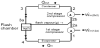
3.8 Multiple Compression Using Flash Chambers
3.9 Diagram of Multiple Compressions Using Flash Chamber
At point 3a, have a mixture of vapour and liquid, which is separated, in the flash chamber (Figure 21). The proportion of the total mass flow that is liquid (and proceeds to the evaporator) is given by:
The remaining vapour mixes with the discharge from the first stage compressor to give different inlet conditions to the second stage.
Assuming adiabatic mixing:
A similar equation can be used to find s2b
Finally the COP is given by:
4. Discussion
Thermal comfort is an important aspect of human life. Buildings where people work require more light than buildings where people live. In buildings where people live the energy is used for maintaining both the temperature and lighting. Hence, natural ventilation is rapidly becoming a significant part in the design strategy for non-domestic buildings because of its potential to reduce the environmental impact of building operation, due to lower energy demand for cooling. A traditional, naturally ventilated building can readily provide a high ventilation rate. On the other hand, the mechanical ventilation systems are very expensive. However, a comprehensive ecological concept can be developed to achieve a reduction of electrical and heating energy consumption, optimise natural air condition and ventilation, improve the use of daylight and choose environmentally adequate building materials [17]. Energy efficiency brings health, productivity, safety, comfort and savings to home owner, as well as local and global environmental benefits. The use of renewable energy resources could play an important role in this context, especially with regard to responsible and sustainable development. It represents an excellent opportunity to offer a higher standard of living to local people and will save local and regional resources. Implementation of greenhouses offers a chance for maintenance and repair services. It is expected that the pace of implementation will increase and the quality of work to improve in addition to building the capacity of the private and district staff in contracting procedures. The financial accountability is important and more transparent. Various passive techniques have been put in perspective, and energy saving passive strategies can be seen to reduce interior temperature and increase thermal comfort, and reducing air conditioning loads. The scheme can also be employed to analyse the marginal contribution of each specific passive measure working under realistic conditions in combination with the other housing elements. In regions where heating is important during winter months, the use of top-light solar passive strategies for spaces without an equator-facing façade can efficiently reduce energy consumption for heating, lighting and ventilation. The use of renewable energy resources could play an important role in this context, especially with regard to responsible and sustainable development. It represents an excellent opportunity to offer a higher standard of living to local people and will save local and regional resources. Implementation of greenhouses offers a chance for maintenance and repair services. Various passive techniques have been put in perspective, and energy saving passive strategies can be seen to reduce interior temperature and increase thermal comfort, and reducing air conditioning loads [18].
Renewable energy is the term to describe a wide range of naturally occurring, and replenishing energy sources. The use of renewable energy sources and the rational use of energy are the fundamental inputs for a responsible energy policy. The energy sector is encountering difficulties because increased production and consumption levels entail higher levels of pollution and eventually climate changes, with possibly disastrous consequences. Moreover, it is important to secure energy at acceptable cost to avoid negative impacts on economic growth. On the technological side, renewables have an obvious role to play. In general, there is no problem in terms of the technical potential of renewables to deliver energy and there are very good opportunities for renewable energy technologies to play an important role in reducing emissions of greenhouse gases into the atmospherecertainly far more than have been exploited so far. But there are still technical issues to be addressed to cope with the intermittency of some renewables, particularly wind and solar. However, the biggest problem with replying on renewables to deliver the necessary cuts in greenhouse gas emissions is more to do with politics and policy issues than with technical ones. The single most important step governments could take to promote and increase the use of renewables would be to improve access for renewables to the energy market. That access to the market would need to be under favourable conditions and possibly under favourable economic rates. One move that could help-or at least justify-better market access would be to acknowledge that there are environmental costs associated with other energy supply options, and that these costs are not currently internalised within the market price of electricity or fuels. It could make significant difference, particularly if, appropriate subsidies were applied to renewable energy in recognition of environmental benefits it offers. Cutting energy consumption through end-use efficiency is absolutely essential. And this suggests that issues of end-use consumption of energy will have to come onto the table in the foreseeable future [19].
The scientific consensus is clear-climate change is occurring. Existing renewable energy technologies could play a significant mitigating role, but the economic and political climate will have to change first. Climate change is real, it is happening now, and greenhouse gases produced by human activities are significantly contributing to it. The predicted global temperature changes of between 1.5 and 4.5 degrees C could lead to potentially catastrophic environmental impacts-including sea level rise, increased frequency of extreme weather events, floods, droughts, disease migration from various places and possible stalling of the Gulf stream. This is why scientists argue that climate change issues are not ones that politicians can afford to ignore. And policy makers tend to agree, but reaching international agreements on climate change policies is no trivial task.
The most favourable orientation, which is due north, results in diminished excessive solar gains through the windows. However, most buildings cannot be oriented at will. If the only possible orientation is due south, and no external shade is used, the index reveals extra heat gains of some 0.26 over the value of totally shaded window. Application of the model results from exploring the relative importance of the thermal inertia of walls, floor and ceiling. Heat stored in building materials, as proven in old, massive buildings, can be compensated during high insolation hours with thermal losses at night and early morning hours, when ambient temperatures are below 25oC. Temperature variation will be lower for higher thermal capacities of building materials. However, it is known while thermal capacity increases the relative importance of individual heat flows change. For example, for lower wall temperatures, the contribution of radiative heat transfer will be reduced, and the relative importance of convective processes will increase, and thus the difficulty to calculate accurately the overall heat flows. The relevance of certain passive techniques is variable with prevailing weather [20].
Finally, the required temperature dependent air transport properties were evaluated by the following expression, which are valid between 2oC and 77oC with temperature expressed in k:
Thermal diffusivity, α = 1.534 x 10⁻³ T - 0.2386 (10-4 m2s-1)
Kinematics viscosity, v = 0.1016 T - 14.8 (10-6 m2s-1)
Thermal conductivity, k = 7.58 x 10⁻⁵ T + 3.5 x 10⁻³ (Wm-1K-1), and
Thermal expansion coefficient, β = T-1 (K-1)
In order to depict the relative contribution of each of these techniques to inside temperature, a dimensionless index is defined as follows. When interior temperature exceeds 25oC, it will be considered as a temperature discomfort condition. This reference temperature is widely elements. Then the following expression:
Is a time function of truncated temperature and it will be able to estimate the overall discomfort by means of the integration along the day for each different scenarios S:
Then, for each passive technique, let:
Finally, the normalised temperature index for each scenario S is:
Naturally, it would be preferred, for comfort reasons that this index would be small, preferably nil. It may be seen that the variable is directly related to temperature discomfort: the larger the value of the index, the farthest will inside conditions be from expected wellbeing. Also, the use of electricity operated air conditioning systems will be more expensive the higher this variable is. Hence, energy expenditure to offset discomfort will be higher when comparing two index values; the ratio of them is proportional to the expected energy savings [21]. When the external shade blocks the windowpane completely, the excessive heat gains belong to the lowest values in the set, and the dimensionless index will be constant with orientation. For the climate conditions of the locality, it can be seen that a naked window can produce undesirable heat gains if the orientation is especially unfavourable, when the index can have an increase of up to 0.3 with respect to the totally shaded window.
5. Conclusion
With increasing worldwide awareness of the serious environmental problems due to fossil fuel consumption, efforts are being made to develop energy efficient and environmentally friendly systems by utilisation of non-polluting renewable energy sources, such as solar energy, industrial waste heat or geothermal water. The GSHPs are suitable for heating and cooling of buildings and so could play a significant role in reducing CO2 emissions. Ground source or geothermal heat pumps are a highly efficient, renewable energy technology for space heating and cooling. This technology relies on the fact that, at depth, the Earth has a relatively constant temperature, warmer than the air in winter and cooler than the air in summer.
A geothermal heat pump can transfer heat stored in the earth into a building during the winter, and transfer heat out of the building during the summer. Furthermore, special geological conditions, such as hot springs, are not needed for successful application of geothermal heat pumps. The GSHPs are receiving increasing interest because of their potential to reduce primary energy consumption and thus reduce emissions of the GHGs. The GSHP is generally recognised to be one of the most outstanding technologies of heating and cooling in both residential and commercial buildings, because it provides high coefficient of performance (COP), up to 3-4 for an indirect heating system and 3.5-5 for a direct heating system.
The main benefit of using the GSHPs is that the temperature of the subsurface is not subject to large variations experienced by air. It is currently the most common thermal energy source for the heat pumps, and so would allow construction of more efficient systems with superior performance. The GSHPs do not need large cooling towers and their running costs are lower than conventional heating and air conditioning systems. As a result, the GSHPs have increasingly been used for building heating and cooling with annual rate of increase of 10% in recent years.
Competing Interests
The author declare that there is no competing interests regarding the publication of this article.