


1. Introduction
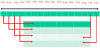
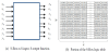
The Advanced Encryption Standard (AES) algorithm defines the underlining cryptosystem in state-of-the-art security systems in vast majority enterprises all over the world. The AES is a symmetric key block cipher cryptosystem in which the encryption and the decryption keys are the same. For surveys on AES, please refer to [1-3]. Researchers made numerous performance enhancements to the AES in terms of area, delay, and power consumption, see for example [4-6]. According to the AES data to be encrypted is divided into equally sized 4 ×4 blocks each is called a state as shown in Figure 1.
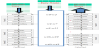
The AES algorithm performs a series (four) of mathematical operations (steps) on each data state based on the Substitution- Permutation (also called the Confusion-Diffusion) principle in eight rounds to produce the cipher text. The AES algorithm starts with an initial step in which it adds the round key to the data state. The state then goes through a loop of four repeated operations: byte-substitution (S-Box) during which every byte is replaced by another one, using the Rijndael S-Box, shift rows (SR) during which every row in the 4x4 array (except the first one) is shifted cyclically a specific number of shift left, mix columns (MC) which is a linear transformation on the columns of the state, and add round key (ARK) during which each byte of the state is combined with a round key using a bitwise XOR. This is followed by a final iteration to produce the cipher text. Similar to encryption, the decryption of a cipher text starts with add round key (ARK) operation. However, the decryption operations are ordered as follows: inverse shift rows (ISR), inverse sub bytes (ISB), add round key (ARK), and inverse mix columns (IMC). The plain (decrypted) text is obtained after a final iteration that excludes inverse mix column operation. An overall illustration of the process is shown in Figure 2 [2]. It should be noted that Round key is different for each round and is derived from the Rijndael key schedule. It is also important to notice that Byte substitution (S-Box) is one of the complex operations in AES.
In Figure 3 we present our taxonomy for the S-Box different realization techniques.
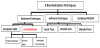
In this paper we cover a number of techniques used for realization of the S-Box. In Sections 2 to 4, we present respectively the hardware, software, and the hybrid S-Box realizations techniques. In Section 5, we present a technique that was introduced earlier by the author [10]. Section 6 presents performance comparison of the different techniques in terms of speed, area, and O(AT2) where A is the area and T is the critical path delay. We then present some concluding remarks.
2. Hardware S-Box Realization Techniques
The S-Box is a nonlinear transformation made by a substitution operation on each of the state independently. The Substitution Table (S-Box) is constructed using two transformations:
-
Multiplicative inverse
-
Affine (over GF(2)) transformation defined by
Which translates to Y=(x4+x3+x2+x+1)*X+(x6+x5+x+1) mod (x8+1)
The multiplicative inverse is complex to perform in GF(28). Composite field (using sub-fields) arithmetic is usually used to simplify the computation, examples include the followings:
- Degree-4: GF((24)2), OR
- Degree-2: GF(((22)2)2)←GF((22)2)←GF(22). This leads to simplified hardware needed for performing the inversion and multiplication operations required for S-Box computation.
The resulting S-Box is shown in Figure 4.
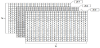
The S-Box can be treated as a multi-input multi-output truthtable that need to be minimized. In this case, the S-Box realization is considered as 8-input, 8-output functions. Each function takes the form Zi =f(x0, x1, x2, x3, y0, y1, y2, y3) where the xi identifies a given row in the S-Box, and the yj identifies a given column in the S-Box. See Figure 5 (a).
If we extract the least significant bits of all S-Box bytes we end up with table Z0. The same idea applies to each of the remaining seven bits. The resulting eight slices of the S-Box is shown in Figure 6.
3. Software S-Box Realization Techniques
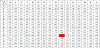
In the software realization of the S-Box, the substitution values are
pre-computed and stored in what is called the “Look Up table (LUT)”.
See Figure 4. The substitution made through the S-Box is done such
that the first right most 4 bits of the data are used to select a row (out of
the 16 S-Box rows) and the last 4 bits are used to select a column (out
of the 16 S-Box columns). The intersection of the row and the column
identifies a cell whose content is the substitution byte. For example if
the original data byte is {b9}
In the series technique, extraction of the S-Box byte is done one byte at a time while in the parallel scheme all 16 bytes are obtained simultaneously. As can be seen the series scheme is slow but requires the least amount of resources while the parallel scheme is the fastest but requires availability of 16 S-Boxes.
4. Hybrid S-Box Realization Techniques
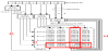
These techniques include LUT software implementations combined with hardware techniques. Pipelining (hardware technique) is used in building the S-Box by employing small substitution tables constructed through LUTs (software technique). The basic idea is that the original large truth-table (the S-Box in this case) of 8-variable functions is broken down into a set of smaller size multiplexer-switched truthtable of n-variable functions using the Shannon expression. The smaller tables are mapped into n-LUT of Xilinx FPGA. An example is shown in Figure 8 [9].
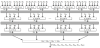
There three stages in this example. The first stage implements Shannon’s decomposition using sixteen 4-LUTs, each having 64-bit string as an input. The results Si, i {1,2,...,16} are latched in the registers of the slices. The second stage uses eight 4-LUTs; each performs the selection between two Sum of Products (SOPs), using combinations of the variables X5 & X6. The results Pj, j {1,2,...,8} are latched in the internal registers connected to the corresponding 4-LUTs. The third stage has inputs generated from the previous stage besides the two variables X7 & X8 which are employed for multiplexing. The results Pk, k {1,2,..., 4} are latched in the internal registers and connected to the corresponding 4-variable OR-function. The whole process can be expressed mathematically as follows:
5. A S-Box Realization Technique using 2×2 Cells
According to this S-Box realization technique byte substitution is performed by using a number of 2×2 tables that are organized in groups. Each group has 16 2×2 cells organized in a bigger table of four rows and four columns. The size of each group is 64 bytes, which is one fourth of the regular S-Box size. The small tables are selected based on row and column values. Each byte needs exactly four groups to cover all values of the original S-Box. If we consider the use of 4 groups, then, 4 bytes can be processed simultaneously [10].
The steps of the new search algorithm can be summarized as follows:
Start the substitution process from the left-most side of the input byte to be substituted and do the followings:
- Use the first two left-most bits of the input byte to select a group of sixteen 2 × 2 cells (one slice)
- Use the next two bits of the input byte to select four 2 ×2 cells within the selected group (one row).
- Use the next two bits of the input byte to select four 2 × 2 cells within the selected group (one column).
- The intersection of the selected row and the selected column produces a set consisting of four 2 × 2 cells.
- Use the final two bits of the input byte to select the output (substitute) byte from among the four bytes.
End of the substitution process.
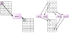
Example: Suppose that it is required to find the byte substitution for the hexadecimal byte {b9}. Figure 9 illustrates the four steps to perform. Notice that the substitute byte for {69} is {56} the same as obtained in Figure 4.
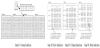
Figure 10 show the overall mapping technique using three 2-4 decoders and one 4-1 multiplexer for the above example. As can be seen, there are four steps. During the first step the two left-most bits are used to select one of the four groups (in this case it is Group #2 (binary 10)) is selected using 2-4 decoder. During the second step the next two bits from the left are used to select one of the four rows (in this case it is row #3 (binary 11)) is selected using 2-4 decoder. During the third step the next two bits from the left are used to select one of the four columns (in this case column #2 (binary 10)) is selected using 2-4 decoder. During the fourth step one of the four cells at the intersection of row #3 and column #2 is selected using the two most bits (in this case byte # 1 (binary 01)) is selected using the 4-1 MUX. As can be seen the selected byte is {56} which is the same as the one done in the example above.
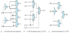
Possible gate-level realizations of the 2-4decoders and the 4-1 MUX are shown in Figure 11.
The novelty of the work presented in this paper stems from the fact that it replaces the search in the 16 × 16 S-Box by a simpler four searches two of them are conducted in parallel such that the search is limited to a set consisting of four 2 × 2 cells which in turn leads to a faster search strategy. We have also provided a simple combinational hardware to carry out the search.
6. Performance Comparison
In this section we provide performance comparison among the different techniques used in the design and realization of the S-Box. In this performance comparison we use the minimum values for the area and delay published in [7] and we also use the CMOS (Complemented Metal Oxide Semiconductor) process characteristics published in [11]. Table 1 illustrates the comparison in terms of the area (measured in gate equivalent GE) and critical path delay (measured in ns).
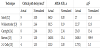
The values presented in the table shows that there is a trade-off between area and the critical path delay. In particular, the following can be concluded:
- The technique due to Bertoni [15] achieves the shortest critical path delay followed by the 2×2 Cells [10], while the Satoh technique [12] achieves the longest path delay.
- The 2×2 cells technique achieves the smallest area followed by the technique due to Canright [14] while the technique due to Bertoni achieves the largest area.
- The normalized AT2 shows that the 2×2 cells achieves the best measure followed by the technique due to Wolkerstorfer [13].
7. Concluding Remarks
In this paper, we have presented a taxonomy of the AES S-Box realization techniques. They include hardware, software, and the combined Hardware/software techniques. A brief coverage of each technique and its sub-classes is then provided. The presentation showed that the hardware-based techniques are classified into composite and combinational techniques. The paper focuses on the combinational hardware sub-class and a comparison among five related techniques is conducted. The comparison is based on the performance of techniques in terms of speed, area and the O(AT2) where A is the area and T is the critical path delay. It was found that the technique due to Bertoni [15] has the shortest critical path delay while the technique due to Abd-El-Barr [10] achieves the smallest area and also has the least O(AT2).
Competing Interests
The author declare that there is no competing interests regarding the publication of this article.