


1. Introduction
Non-portable dynamometers have been widely used for the strength assessment of the lower limb muscles [1-3] . Technical difficulties such as inability to transfer to the clinic, do not allow the use of nonportable dynamometers. For that reason hand-held dynamometers have been used [4-6] . However, the literature showed that there are a number of reasons which discourage the use of hand-held dynamometers in the muscle assessment of the lower limb muscles. These were their low reliability [7], the absence of comparisons with other gold standard dynamometers and the question about the number of trials needed to decrease the systematic bias [8]. A recent study reports high reliability (ICCs = 0.83-0.92) when testing different groups of the lower limb [9] however, they reveal low reliability for knee extensors (ICC = 0.60). Knee extensors can produce intense contractions and their inter-rater reliability [8]. For the above reasons a new method to assess muscle strength was designed using a load cell (PowerLab/16SP; ADInstruments, Castle Hill, Sydney, Australia) and two chains attached from both sides to assess lower limb muscle strength.
3. Aims
The aim of this study was to investigate whether a portable dynamometer (load cell plus Power lab© software) could be used as a reliable and valid way of measuring lower limb strength. Thus, it was decided that reliability (test re-test, intra-rater) and reproducibility of the portable dynamometer would be assessed along with the validity when the portable dynamometer was compared with the (gold standard) non portable dynamometer Humac Norm© (Humac Norm Model 770; CSMi, Stoughton MA, USA) in four isometric lower limb tests.
4. Materials and Methods
Twenty health individuals (9males and 11 females), with no lower limb conditions participated in this study. Participants, were students and staff of the local university (EUC, CY) and were asked to perform four isometric strength tests in a portable and non-portable dynamometer. Participants were informed about the study by word of mouth and when interested they received a participant information sheet by the researcher. All participants had at least 24 hours to decide about their participation. At the first testing day a consent form was received by all participants.
4.1 Participant inclusion criteria
- No pain on the tested lower limb leg
- Ability to attend both sessions
- Ability to consent for themselves
Participants who did not meet the inclusion criteria were excluded from the study. All participants were asked to visit the physiology laboratories of the School Sciences on two occasions. The second session was at least a week after the first session. The second time was at least a week after the first session (average time between sessions 9.2 days). During the first session, the participants performed strength tests using their dominant leg measured by the portable dynamometer and later they performed the same tests measured by the non-portable Humac Norm©. In the second session they performed strength tests measured by the portable dynamometer only.
4.2 Ethics consideration
The study was approved by the School of Sciences ethics committee of European University Cyprus.
5. Calibration
Before testing took place, both portable and non-portable dynamometers were calibrated. In order to maintain data integrity technicians from the School of Sciences calibrated the Humac Norm© according to the manual of the isokinetic dynamometer. Same technicians also calibrated the load cell of the portable dynamometer. A 5 kilogram free hand weight was attached to the load cell with a chain and the load cell was then set to show 5 kilogram push force.
There was a familiarization session a day before the first trial where participants were told what they had to perform the next day. In addition, they performed a series of MVCs of all the strength tests on both isokinetic and portable dynamometer.
6. The portable dynamometer
The portable dynamometer (AD Instuments PowerLab/16SP©, Australia)was attached to ADInstuments Bridge Amp FE221 and the latter was then attached to an ©RS load cell, model 615 (©RS Components Ltd, UK). Two metal chains were connected from both sides of the load cell. One chain was stabilised to the bars that the physiotherapy couch had underneath, and the other chain that was also attached to the load cell ended in a loop shape. This loop was covered by soft material (pipe insulation material). Participants were asked to put their leg into the loop and push away. The leg tested was the one that participants considered as their ‘strong’ one. The direction participants had to push was always vertical to the load cell. Participants put their leg into the loop and the examiner stretched the chain to its end with his hand passively. Then the examiner set all measurements to zero. This had to be done before every single trial. Performing this, the examiner achieved to exclude the confounding factor of the chain weight or chain noise. There was no force caused by the examiner as when the participants were asked to push, the examiner got his hands off the chain. All participants were measured in the morning and both measurements were done at the same time of the day. Participants were asked whether they performed any exercises the day before and whether they felt weak or had any residual pain at the day of the examination. Participants who did not comply with those requirements were excluded from the study.
7. The isometric tests
Four isometric, lower limb strength tests were performed by all participants in both portable and non-portable dynamometers. The tests measured the strength of the knee extensors (test 1), the abductors (test 2), the external rotators (test 3) and the combination of both external rotators and abductors (test 4). In each of the tests, 3 isometric warm up tests approximately at 25%, 50%, and 75% of maximal strength were followed by four MVCs. Only the strongest MVC was recorded. There was a 30 seconds rest between contractions and a two-minute rest between tests.
The tests were performed in the non-portable dynamometer as explained below:
7.1 Isometric knee extension test (test 1)
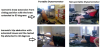
Participants were placed in a sitting position with the knee extended at 60 degrees from full length extension and asked to forcibly extend their knee against the dynamometer. The hip was flexed at 90 degrees whilst the trunk, pelvis and foot were strapped tight with belts [10] (Figure 1a).
7.2 Isometric hip abduction test (test 2)
The participant was placed in the side-lying position on the isokinetic dynamometerwith the tested leg uppermost and the other knee flexed at 90 degrees. The spine and pelvis were then placed in neutral alignment and stabilised by the researcher’s hands whilst the tested leg was strapped with the isokinetic dynamometerlever arm at 30 degrees of abduction. The participants put one hand under the cushion where they put their head and the other hand held the handle under the bed. Then, they forcibly abducted their leg against the resistance of the dynamometer [11] (Figure 1a).
7.3 Isometric hip external rotation test (test 3)
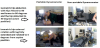
In the supine position with both knees fully extended and the tested leg externally rotated to 5 degrees, the participant was asked to rotate the foot externally against the resistance of the dynamometer. The pelvis and the tested knee were strapped with belts as no pelvic movement or knee flexion was allowed [12] (Figure 1b).
7.4 Isometric hip abduction from ‘clam’ test position (test 4)
The ‘clam’ position was performed in a side lying position with the knees flexed at 90 degrees, the hips flexed at 60 degrees and the feet tied together with a belt. The tested leg was then abducted to 30 degrees and the participant was asked to push against the resistance of the dynamometer. The feet were strapped together with a belt; the belt kept the feet together but it did not put any resistance to the contraction. The researcher stabilised the pelvis whilst the participant held a handle with one hand which was positioned under the isokinetic dynamometer bed [11] (Figure 1b).
The tests were performed in the portable dynamometer as explained below:
7.5 Isometric knee extension test (test 1)
The test was performed with the knee extended to 60o from leg extension [10]. Participants were position sitting on the physiotherapy couch with their knees off the edge of the bed. A soft cylinder shaped material was placed under their knees, so that there was no pain during the contractions. Seven trials were performed on each participant. Participants placed their hands behind their back to hold the end of couch. The loop with the force transducer was placed around the distal tibia, just above the ankle (Figure 1a).
7.6 Isometric hip abduction test (test 2)
The test was performed with the tested knee extended and the hip abducted to 30o [11]. Participants were lying on the side with the tested hip on the top. Trunk, pelvis and the top lower limb was in alignment, whilst the other leg was flexed to support participant stability during contractions. The loop was then placed around the distal portion of the top of the thigh, just above the knee (Figure 1a).
7.7 Isometric hip external rotation test (test 3)
The test was performed with hips flexed to 60o and knees to 90o and the hip abducted to 30o [11] Participants from side lying position with the tested leg on the top, performed 7 isometric contractions (3 warm ups and 4 MVSs). The researcher stabilised the pelvis in order to inhibit any backwards movement. The loop was placed in the same position as in the previous test (Figure 1b).
7.8 Isometric hip abduction from ‘clam’ test position (test 4)
The test was performed with leg fully extended and rotated to 5o from supine position. Participants were positioned lying on their back with the heel of the tested leg in a hole that the physiotherapy couch provides [13,14]. The chain was attached tight around the training shoe whilst, the pelvis and the tested leg thigh was strapped to the couch to inhibit any movement or flexion. When participants rotated their hip to 5o the chain was tight (Figure 1b).
During the trials, participants had no visual feedback as the monitors were out of their sight. Before they perform the tests the investigator provided them with clear instructions regarding how long they had to push for, in what direction and how hard. The only verbal instruction participants received by the investigator was the word ‘go’ just at the time they had to perform the strength tests.
8. Statistical analysis
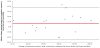
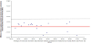
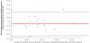
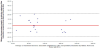
Independent t-Tests were conducted between contractions measured by the portable and non-portable dynamometersto identify any differences between participants’ performance. To measure the ability of the portable dynamometerto report similar results under the same conditions, intra-class correlations coefficient (ICC) was conducted between the results of the first and second session to test reliability. In addition, paired t-Tests were also performed to identify any differences. Finally, to assess validity of the new dynamometer, 4 Bland and Altman plots were created to show correlation of performance with the non-portable dynamometer.
The Bland and Altman plot is a statistical method for assessing agreement between measurements [15]. The measurements can be plotted against one of the two methods [16] (gold standard method); in this case the non-portable (Humac Norm©)isokinetic dynamometer results. Each plot is comprised of an x axis which reports the average MVCs measured by the two dynamometers and a y axis which shows the differences between the MVCs. Each plot has 3 lines; one for mean (red middle line), and two discontinuous lines which are defined as the mean difference plus and minus 1.96 times the standard deviation (± 95% limits of agreement).
Measurements gained from the non-portable dynamometer were reported automatically in N/m (Newtons/meter) whereas; measurements from the portable dynamometer were in N (Newtons). Therefore, the distance between the joint which produced the force and the position of the loop of the lower limp was measured for all tests in order to convert measurements to N/m (torque).
9. Result
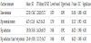
The study was performed from May to July 2013. Twenty healthy controls took part in this study (11 females and 9 males). Their age was 22.6 ± 3 years, height 1.72 ± 0.11 m and weight 73.78 ± 13.18 kg. There was no differences (p<0.05) between the performances of any of the strength tests measured by the two dynamometers. Table 1 presents the lower and upper bound, T values, means ± SDs and p values for both dynamometers in the tests measured.
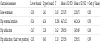
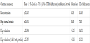
Reliability analysis revealed strong ICC (above 0.9), whilst the paired t-Tests showed no significant difference (p<0.05) between the MVC results of the first and second session of the portable dynamometer for all of the tests; refer to table 2.
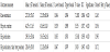
To identify the validity of the new portable method to assess strength, the results of the portable dynamometer were correlated with those of the non-portable isokinetic dynamometer and ICC was reported (Table 3). Strong correlations were found for all four strength tests; therefore, strong validity of the portable dynamometer was determined. Table 4 reports the confidence interval, mean bias, Standard Error (SE) of differences, whilst, one Bland and Altman plot for each test was created showing the comparison of the two techniques. The Bland and Altman plots also showed high correlations between the isokinetic and the portable dynamometer (Figures 2-5).
10. Discussion
Previous literature review did not show any similar ways of measuring muscle strength in a clinical environment. Therefore, the assessment of the portable dynamometer regarding its reliability and validity was crucial but also innovative. The current study has shown that the portable dynamometer using a load cell can be reliable and valid in measuring the strength of knee extensors, hip abductors, hip external rotators, and the combination of hip abductors and hip external rotators (‘clam’ position). Most of the previous studies have tested hand-held dynamometers regarding their test-retest and interrater reliability of the knee extensors only; [17,18] or hip abductors/ adductors [19], while there is no much evidence regarding rotator muscles of the lower limb. Reliability of hand-held dynamometers measuring the strength of the lower limb has been found to vary across studies. Recent studies have shown that hand-held dynamometers can have high inter-rater reliability [18] however the measurements should preferably be taken by a fixed hand-held dynamometer than a non-fixed one. On the other hand, other authors [17] reported also reported high inter-rater reliability however they revealed wide limits of agreement pointing out that the tester strength is paramount even in frail populations such as patients with cancer. Hand-held dynamometers need the examiner to keep hands steady regardless of the force. This is extremely difficult especially when the participant is strong. This is probably why previous research showed that portable dynamometers revealed lower reliability when testing the lower limb [7] compared to upper limb. In addition, Bohannon [20] reported that a hand-held dynamometer is a reliable procedure but needs to be used by a clinician who is experienced with the technique. The use of the current portable dynamometer technique did not need any specific experience and enabled more precise measurements than a common hand-held device. Interestingly, results of the current study have shown that the portable method was reliable and valid enough to measure isometric muscle strength from four specific positions. The advantage of the portable dynamometer was that the measurements do not depend on the researcher. The disadvantage of this method was that the time needed in order to set up the equipment for each test is longer than a hand-held dynamometer. Additionally, the increased bias that was found from the Bland and Altman plots should also be considered. Although the validity of this method was assessed by comparing the results with a non-portable gold standard dynamometer (suggested by Stockton et al. [8] the number of trials that took place were not enough to decrease the bias. More trials would have perhaps provided clearer data, as any learning effect if shown would then be excluded.
11. Conclusion
The portable dynamometer system was found to be reliable and valid to measure lower limb strength from four different positions. This system could widely be used in research or clinical environments where isokinetic dynamometers do not exist or cannot be transferred to. The measurements are precise however; the procedure is time consuming (when the portable dynamometer has to be set up from scratch) compared to hand-held dynamometers. The cost of such a portable-dynamometer is significantly less than an isokinetic dynamometer but it costs more than a handheld-dynamometer.
Competing Interests
The authors declare that they have no competing interests. The author declare that there is no competing interests regarding the publication of this article. The authors have no competing interests with the work presented in this manuscript.