


1. Introduction
The cooling system of plateau engineering machinery needs a special design as at high altitude it will confront the climate of rarefied air, low pressure and coolant boiling temperature, large temperature difference of day and night. In such a hostile working environment, engine fuel burning will deteriorate and more heat will be generated whereas air mass flow rate of cooling fan will decrease and heat transfer in heat exchanger will be incomplete. Consequently, the engine will be overheat, which will badly affect machine operation and even lead to a serious failure [1,2]. Designing a cooling system to ensure the machine working at good condition in plateau region has become upscale project of engineering machinery enterprises.
Since 1960, researchers and enterprises have paid attentions to plateau engineering machinery and have gained remarkable achievements. Caterpillar and Komatsu firstly pushed out plateau products in 1970 and 1980, respectively [3,4]. Afterwards, most famous foreign enterprises (such as JCB, Case, Mitsubishi Heavy Industries and so on) also started the exploration of plateau engineering machinery and entered in this product field gradually. Till now, they have also mastered their independent technologies and built a series of principles [5,6]. On the contrary, most domestic companies cannot qualify in this market. One of the reasons is that the cooling system cannot afford engine to work effectively for a long time.
The vehicle cooling system usually includes engine, thermostat, water pump, expansion tank, fan, heat exchanger, pipes and other units, among of which heat exchanger is the most important component. The heat exchanger is in charge of heat dissipation and its design is closely concerned with the performance of cooling system. Due to the worse climate, plateau heat exchanger should be more efficient in the same operating condition than that of plain type. However, most researches focus on heat transfer and flow analyses of heat exchanger in plain region, but there are few on plateau region. Therefore, in order to manufacturing a high quality and reliability plateau engineering machinery, this paper concentrates on the characteristics of plateau heat exchanger.
2. Simulation of Plateau Heat Exchanger with Different Fins
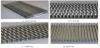
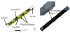
In order to enlarge heat dissipation area with a requirement of size and weight, heat exchanger is always adopting augmented surface and there are four typical fin configurations on common use: louvered, wavy, offset and plain fin as shown in Figure 1 [7]. Hence, the paper begins with the choice of fin type used in plateau region.
2.1 Heat transfer and flow characteristics of different fins
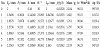
The performance of heat exchanger is closely concerned to local air condition. The change of altitude will greatly influence air density, local pressure and water boiling temperature. In MATLAB software, the characteristics of heat transfer and flow resistance of different augmented fins in various altitudes were simulated. The model used the fin geometries of Table 1 with working conditions of 10m/s air flow rate, 0.001m3/s coolant flow rate, 27°cooling air inlet temperature and 90° coolant inlet temperature.

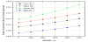
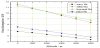
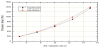
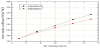
Since air pressure also decreases with altitude, the pressure drop of various altitudes should be processed for a normalized comparison. Here the ratio of pressure drop to local air pressure is used as shown in Figure 2. With altitude increase, the ratio of each fin also increases. For the same altitude, the ratio of louvered fin is larger than the others because of its special configuration, which implies that the flow resistance of louvered fin is the largest. Figure 3 shows the heat dissipation of different fins. It can be observed that once the altitude is larger than 2km, louvered fin proves good heat transfer ability compared with the others, especially at high altitude. Meanwhile, for every one kilometer rise in altitude, heat transfer amount of same dissipated area with louvered, wavy, offset and plain fin drops about 0.4, 0.3, 0.6 and 0.5kW, respectively. Based on these results, the ratios of enlarged heat dissipation in plateau region for different fins compared with that in plain region are arranged in Table 2 for a more clear demonstration. It can be seen the configurations of wavy and louvered fin are more adaptable in different regions as the ratios of the two fins are smaller than the others. That is in plateau area the two fins will be the prior considerations as they suffer less change of the system due to their good heat transfer ability.

2.2 Comprehensive evaluation factor of different fins
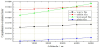
An ideal heat exchanger possesses high heat dissipation but low flow resistance. However, the two characteristics are contradictory in many aspects. For example, the pressure drop of plain fin is the smallest while its heat transfer is not as good as louvered fin. For the sake of designing and manufacturing a good heat exchanger both taking heat transfer and flow resistance into consideration, the comprehensive evaluation factor j/(f1/3) is used to estimate the equipment [8]. Here, j is Colburn heat transfer dimensionless factor which is calculated by:
where: ρ is air density; cp is specific heat capacity at constant pressure; u is air velocity among fin; h is heat transfer coefficient of fin; Pr is Prandtl number. And f is fanning friction factor, which is calculated by:
where: Ac is minimum free flow area for air side; Ao is total air side surface area; Δp is pressure drop; kc is abrupt contraction pressure loss coefficient; ke is abrupt expansion pressure drop coefficient. According to the results in Part 2.1, the comprehensive evaluation factor is calculated and shown in Figure 4. Below altitude 3.5 km, the heat exchanger with offset fin demonstrates the best ability, whereas above 3.5 km the louvered fin shows its great comprehensive performance. Therefore, for an overall thinking about comprehensive performance and configuration, the heat exchanger with louvered fin is the first choice in plateau area.
3. Thermal Balance Experiments and Results
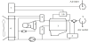
The cooling system of finished engineering machinery is shown in Figure 5. The experiments were about thermal balance tests. Seven thermometers were respectively fixed in cooling water inlet of heat exchanger, cooling water outlet of heat exchanger, air inlet of heat exchanger, air outlet of heat exchanger, air filter inlet, exhaust outlet of engine and atmospheric environment. The thermometer setting should be ensured that all testing equipments were not contact with system rotation parts.
3.1 Thermal balance experiments
The experiments were carried out in a sunshine day as shown in Figure 6. First it worked at null load for warming-up. During warming-up, it should be inspected about leakage of water, engine oil, diesel oil and so on. Till water temperature maintained at a point for a period of time, the engineering machinery operated at full load and testing results were collected by a multi channel recorder. The outdoor experiments lasted for about 1.5 hours.

3.2 Experimental results
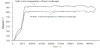
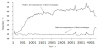
Figure 7 shows the inlet and outlet coolant temperature of heat exchanger. The inlet coolant temperature grew quickly from surrounding temperature until about 91° when the system was operating at a balanced condition. The outlet coolant temperature was almost the same whereas its value was only up to about 81°. Figure 8 shows the inlet and outlet air temperature of heat exchanger. The inlet air temperature was higher than surrounding temperature as inlet thermometer was fixed in inlet grids of engine compartment hood but not in atmospheric environment and there was heat stack in the hood. The temperature curve of outlet air was not so smoothing, but it can be seen that outlet air temperature of heat exchanger gradually increased and kept at a point of 62° when the system worked normally.
4. Further Analyses and Optimizations of Heat Exchanger
The experiments were all carried out in plain region. Therefore, although inlet coolant temperature of heat exchanger (outlet coolant temperature of engine) was not beyond 100° the system is considered to be further upgraded for plateau region. This is because water boiling temperature will decrease at high altitude. As a result, the system should be promoted. The heat exchanger is in charge of cooling down working fluid from engine water jacket in system cycle. Its design is closely concerned with the performance of cooling system. Therefore, the optimization is focus on the analysis of heat exchanger.
4.1 Theoretical calculations and comparisons
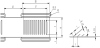
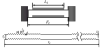
The tube heat exchanger with louvered fin is used above and its geometry and configuration are shown as below in Table 3 and Figure 9.

The model of heat exchanger is shown in Figure 10. When the air flows through the exchanger from air inlet, the heat of coolant is taking away by heat convection of tube wall, heat conduction of tubes and fins and heat convection of fins surface. Then the model was imported into ANSYS Workbench. Its boundary condition is: uniform flow velocity in air inlet; pressure outlet in air outlet; fluid coupled with solid condition for the interface of air and louvered fin; uniform temperature of 363K for water tube wall; periodically symmetry plane for the other walls. Since the air flow is supposed to be constant-property, incompressible and non-viscous, the control equations can be simplified to be:
where: ρ is air density; cp is specific heat capacity at constant pressure; V is air velocity vector; P is the local air pressure; T is temperature; λ is thermal conductivity.
In order to verify the rationality and reliability of the simulation, first the simulation was carried out according to the conditions of Reference [9]. The comparisons of pressure drop and air heat transfer coefficient between simulation and experiment are shown in Figure 11 and 12. In Figure 11, the two curves agree well for the whole range. However, in Figure 12 the error of simulation and experiment increases with the air velocity. This may be because with the increase of air velocity, the turbulence of air flow aggravates and the situation deviated the initial setting, in addition to accounting for all instrument errors, property uncertainties and geometry tolerances. But the average error value is about 6.8% and the working air flow velocity is always smaller than 12m/s, therefore the simulation is considered to be reliable and useful.
4.2 The Optimization of heat exchanger with louvered fin
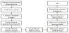
Since the performance of heat exchanger is affected by many parameters and some of them play opposite part in different characteristic. For instant, increasing surface area will improve heat transfer ability, whereas it will enlarge the whole size. Consequently, the optimization of heat exchanger is aiming at its overall performance and adopts multi objective optimizing method to achieve the target. Here the target functions are comprehensive evaluation factor j/(f1/3) and heat exchanger mass. The calculated process is shown in Figure 13. First, determinate the key parameters according to heat exchanger structure and then import the 3-D Solidworks model into ANSYS Workbench (AWB). Second, determinate the experimental points in Central Composite Designs and then use AWB CFX simulating module to conduct Fluid-Solid Coupling calculations. Third, run Goal Driven Optimization module to get the result point and then use Shifted Hammersley Sampling Method to extract the sample points for the initial population of genetic algorithm, which are equally distributed in n-dimension feasible solution area. Fourth, establish the simulation model with comprehensive evaluation factor j/(f1/3) and heat exchanger mass as optimized objectives, air heat transfer coefficient and pressure drop as constraint function and structure dimension as experimental variables. Finally, carry out the simulation using the multi objective genetic algorithm and then find out the best Pareto solution.
Here the key parameters used in simulation were: fin pitch Fp, fin length Fl, fin thickness δ, louver angle θ and louver pitch Lp, which were shown in Figure 14. Using the original heat exchanger described above, the initial simulation was carried out, from which it was obtained that the comprehensive evaluation factor was 0.013276 with the heat exchanger mass of 0.0021041kg, air pressure drop of 997.93Pa, heat transfer coefficient of 96.51W/(m2∙K). Based on these results, run multi objective optimization program and Pareto solutions gained are shown in Table 4, where the initial configuration of louvered fin is marked as No. 0 and the new designs from optimization are marked from No. 1 to No.6.
4.3 The sensitivity analyses of heat exchanger with louvered fin
In order to find the better structure dimension from Pareto solutions of multi-objective optimization, the sensitivity analyses of five parameters are carried out. The results are shown in Figure 15 and Figure 16. In the two figures if the value of vertical coordinate is positive, the corresponding parameter in horizontal coordinate is positive proportion to target parameter. Taking the heat exchanger mass as example, it will increase with the increasing of fin pitch, fin thickness, fin length and louver pitch but the decreasing of louver angel. Meanwhile the bigger the value of vertical coordinates is, the more sensitive the corresponding parameter is. In Figure 15, it can be seen that the comprehensive evaluation factor is greatly affected by the parameters of fin pitch, fin thickness and louver pitch, where fin thickness and louver pitch are positively correlated but fin pitch is negatively correlated. From Figure 16, it can be seen that the mass of heat exchanger is greatly affected by the parameters of fin pitch, fin thickness and fin length, where the three parameters are all positively correlated.


4.4 Further discussions
According to all analyses above, the best way of improving overall performance of heat exchanger is decreasing fin pitch and fin length and then increasing louver pitch for the increase of comprehensive evaluation factor but decrease of heat exchanger mass. Here the paper recommends the optimized system of No. 1 and No. 2 in Table 4 because the mass of No.1 can be even decreases 20.06% and the comprehensive evaluation factor of No. 2 is the biggest of the six optimized structure. The further experiments with optimized heat exchanger in plateau region will be carried out in future.
5. Conclusion
This paper presents heat transfer and flow characteristics of heat exchanger with different fins in plateau area. Four extensive-use fins are studied and it is found out that heat exchanger with louvered fin possesses nice comprehensive performance and configuration in the whole calculated region especially at high altitude (above 3.5km), so that it is the prior choice in plateau area for an overall thinking. Next, the designed cooling cycle with louvered fin heat exchanger was tested in plain but experimental results indicated that the cooling system should be upgraded for a higher efficiency. Then the research focuses on the promotion of heat exchanger with louvered fin. The theoretical calculations and simulations are validated to be reliable and effective as the results agree well with previous experiments. The multi objective optimization and sensitivity analyses method are adopted for the system promotion. The best way of improving overall performance of heat exchanger is decreasing fin pitch and fin length and then increasing louver pitch for the increase of comprehensive evaluation factor but decrease of heat exchanger mass. One of the optimized systems is improved with 2% increase of comprehensive evaluation factor but 20% decrease of overall mass, which means that for the same volume and mass the optimized heat exchanger can greatly enhance its capacity of heat transfer. The further experiments with optimized heat exchanger in plateau region will be carried out in future. This research will be helpful in guiding future design and optimization of plateau engineering machinery.
Competing Interests
The authors declare that they have no competing interests.