


1. Introduction
Transformers are important devices for the electric energy transmission and distribution through the grid. These devices transfer energy from one circuit to another by a common magnetic field. The transmission of electric power along vast distances at low voltage is not economically feasible because the losses are tremendous [1]. On the other hand, the power generation and consumption cannot happen at high voltages since they need pronounced insulation for safety operation. For that reason step-up transformers are needed to raise the voltage after the generation for transmission and then step-down transformers take the voltage to an appropriate distribution level [2]. The power generation is usually obtained in a range from 11 to 33 kV, and then it is supplied to the transport network at 150, 220 or 400 kV in AC and 550, 800 kV on high voltage DC [3]. The consumption occurs typically at 230/420 V. The energy is transferred between the low voltage and high voltage circuit by the magnetic induction principle. The majority of the transformers work in three-phase, so they have 3 sets of 2 bobbins each that are lagged 120o from each other.
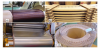
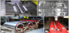
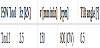
The winding coils can be assembled in different forms as represented in Figure 1. The wired winding coils are used in small distribution transformers. Different solutions for winding coils are used in power transformers applied at voltages from 15 to 765 kV and higher with ratings stated in MVA. The power transformers have high short-circuit duties with a variable thermal loading that can be severe in some cases.
The variance in cost between of electrical transformers with copper versus aluminium conductors is now affecting the customer’s buying decision. Thus, pending on the market cost of copper, the manufacturers of electrical transformers are replacing by aluminium several massive conductor components originally made of copper, as stated by Paul et al. [4]. The lower conductivity of the aluminium ( 3.5 0 x107 S/m is the commonly used for high voltage power line) compared to copper ( 5.96 x 10⁷ S/m) does not means that the aluminium conductor will run hotter than the copper conductor, but does means that the aluminium conductor for the same ampere rating must have a larger cross sectional area. When density of copper (8930 kg/m3) is compared to the one of aluminium (2700 kg/m3) and taking into consideration the conductivity ratio of aluminium to copper, the result shows that on a per kg basis, aluminium has an amperage capability from 1.64 to 1.85 times higher than that of the copper. In according to Sullivan [5], even considering the less resistance of aluminium to thermal, chemical and mechanical loadings, and all the issues related with the need of dissimilar joining with terminals made of copper, the aluminium is nowadays a significant trend in the production of winding coils for transformers in power systems.
Now days, the main welding process applied to copper winding coils is the GTAW (Gas Tungsten Arc Welding). This welding process is effective in welding the copper components, however, some defects occur when applied to aluminium, namely, porosity, hot cracking and non-acceptable residual deformations. The prevention of distortion is an important requirement to avoid short-circuits between the multiple turns of the windings with small gap distance. As emphasized by many authors, namely Golubev et al. [6] and Fehrenbacher et al. [7], the solid-state Friction Stir Welding (FSW) process is already a well-established solution for welding aluminium alloys, resulting in low distortion joints. A comparison between the TIG with the FSW process in the joining of copper alloys was presented by Lin et al. [8], confirming that the copper alloys joined by FSW presents better overall performance than welded by TIG. Lohwasser et al. [9] considers that aluminium alloys are particularly suitable for being solid state welded because they are characterized mechanically by a relatively low flow stress in the viscoplastic zone, i.e. the zone undergoing temperatures above recrystallization temperature and below melting temperature of the material. Pépe et al. [10] concluded about the fatigue and corrosion resistance benefits for AA5083-H111 of the zone under direct mechanical processing of the non-consumable FSW tool. This thermo mechanical processed zone undergoes a severe thermo-physical cycle resulting in dynamic recrystallization and consequent grain refinement and homogeneous fine distribution of hardening particles. Leitão et al. conclude similar benefits for 1 mm thick aluminium plates [11], where the processed zone of the aluminium alloys AA5182-H111 and AA6016-T4, presented benefits when compared with original condition. Several studies can be found in FSW of commercial pure aluminium thin sheets, namely the ones presented by Topic et al. [12], and Sato et al. [13], but none of these used a partially annealed temper condition, with low hardness, as the one welded in the present application.
This paper describe the feasibility analysis of application of FSW to join aluminium foil winding coils towards a significant addvalue application on the scope of the production of components for electrical transformers. The FSW is applied to join residual bobbins of aluminium sheet AA1070 with 1.6 mm thick and 1100 mm wide. In a sequential procedure, two residual foil winding coils are butt jointed by FSW and rewound in one new longer bobbin, until the total length already enables its reutilization. Via this method, in the present tested application, six residual foil winding coils were transformed into 2 new foil winding coils each one gathering three original residual foil winding coils. The development of the technological conditions and supporting systems is depicted.
Moreover, the mechanical and basic metallurgical and electrical features are established for the preliminary experimental tests (Task 1) and final implemented conditions (Task 2).
2. Requirements for the FSW application
The requirements for the properties of the foil winding coils welded by FSW, focus on residual deformation and geometry, mechanical resistance and electrical resistance of the weld zone. The established criteria were:
- The weld joint should be complete over all the original width of the base material coils, because the magnetic fields around the side edges of the coils are particularly important;
- The residual deformation should be low, namely: a) No sharp geometrical discontinuities along at the face and root of the weld joint; b) No thickness variation over 5 % of base material thickness; and c) No out-of-plan distortion over 5 % of base material thickness;
- The maximum load capacity of the welded zone should not under match the base material properties in tensile tests and bending tests. No special requirements for elongation and toughness because the real loading condition is static bending with no impact loads;
- The electrical conductivity in the weld zone should not be less than 5 % of base material electrical conductivity.
3. Experimental Conditions
3.1 Base material
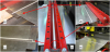
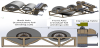
The base material was a technically pure aluminium AA1070 with a chemical composition of 0.08 wt.%Si, 0.23 wt.% Fe, 0.01 wt.% Cu, 0.004 wt.% Mn, 0.01 wt.% Mg, 0.004 wt.% Cr, 0.02 wt.% Zn, 0.01 wt.% Ti (all the contents are maximum limits) and 99.70 wt.% Al (minimum content). This material typically appropriate for electrical conductor components was supplied in the shape of laminated sheet with thickness, t = 1.6 mm, and width, w = 1100 mm. The plates were stored in foil winding coils around a paperboard tube with internal diameter, Øint = 400 mm. Six residual foil winding coils were received at the welding laboratory, with weights ranging from 200 to 300 kg.
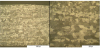
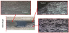
The Figure 2 shows the original foil winding coils as received at welding laboratory and the metallographic analysis of the base material cold rolled and partially annealed foil in the as-received condition. This sample has been prepared according to the procedure described below, and etched with Poulton reagent to reveal grain boundaries. The anisotropic structure, originated by cold rolling operation, does not show evidence of any presence of precipitates and second phase particles.
The mechanical properties of base material were tested for tensile and bending resistance. An average of 3 specimens extracted along the rolling direction was calculated. The values obtained are depicted in Table 1 for the tensile resistance properties, namely, Young modulus (E), yield strength (σ02), ultimate strength (σu), specific toughness (ET) and elongation at fracture (ε).
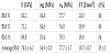
The values presented in Table 2 for the bending resistance properties depict the maximum force during test (Fmax), displacement of puncher at maximum force (Dmax) and energy applied until maximum force (En).
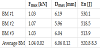
The hardness of the base material was tested, with 2 sets of 9 points, and the average was BMHARD = 27.9 HV02.
3.2 Plan for joining the foil winding coils
The FSW joints were performed in 2 sequential tasks, represented in Figure 3, and described below:
Task 1) Preliminary test trials to develop the FSW process parameters and technological conditions were performed on 300 mm long welds. This length already includes the all initial and end zones with transient conditions and a stationary zone at the middle of the weld joint. These tests were performed in the original table of the FSW equipment. During these preliminary tests the best set of FSW process parameters and tool features are developed and selected for implementation in real conditions of Task 2;
Task 2) Final tests in conditions similar to the real industrial application conditions. For this purpose a new dedicated supporting and clamping system was designed to test the welding and rewinding of the foil winding coils in real dimensions. The new dedicated supporting and clamping system was built only to assess the feasibility of this application of FSW. Thereof, to minimize the cost, the design was based on a hybrid structure made of wood (for the overall structure), steel (to support with high stability the load and dynamics during the FSW process) and copper (as cool backing anvil).
All the welds were performed in the direction transversal to the rolling direction of the aluminium foil. During Task 2 the plan for joining the original residual foil winding coils is presented in Figure 4. For each welding pair of foil winding coils the heaviest coil before joining was positioned in the back bobbin support. This criteria are due to the fact that back bobbin support was designed to be stronger than the front support of the foil winding coils. Therefore, the rewinding direction after joining by FSW was always oriented into the back bobbin support.
4. FSW Equipment and Tools
The FSW equipment applied is an ESAB LEGIO 3UL. This equipment enables vertical downward force control of the FSW tool relatively to the workpieces, and online capacity of computational monitoring of all the welding parameters, including force, torque, position and speed in all the axis (the monitoring and records were done with 10 Hz).
The FSW tool geometric features of the probe and shoulder are the main process parameters. The architecture of the FSW tool used to perform the welds is a patented [14] modular concept. This tool enables easy replacement of any damaged component and the combination between different shoulder and probe geometries. The shoulder and probe modules of the tool were made of AISI H13, quenched and tempered up to a hardness of 52 HRC. Ionic nitriding and oxidizing were further employed to enhance the final hardness (up to 72 HRC) and its resistance to corrosion, respectively.
Two different tools were tested in this work. The geometric features of the two tools: a) Tool 1; and b) Tool 2, are described and represented in Table 3.
5. Procedure for FSW Tests and Production
To respect the first requirement for the properties of the foil winding coils welded by FSW, and to avoid the residual hole at the exit of the FSW tool, and the initial and final transient properties of the FSW joints, during the set-up for FSW, two tabs were included, as depicted in Figure 5. Namely, one run-on tab at the start of the weld bead, and one run-off tab at the end of the FSW bead. The run-on and run-off tabs were extracted from the base material of the foil winding coils, with about 100 mm x 100 mm. The weld joint started inside the run-on tab, 50 mm before the coil, and ended inside the run-off tab, 50 mm after the end of the coil.
The run-on and run-off tabs are extracted after unclamp the welded coils. After extraction of the tabs, the layers were carefully aligned and rewinded under strong tension disabling gaps between layers. A separation paper is introduced in between all the layers during the rewinding into the new foil winding.
The FSW process parameters implemented in production of the final welds in Task 2 were the ones present in Table 4. All parameters are result of a preliminary development procedure based on visual analysis, hardness tests, tensile tests and bending tests. The vertical forging force at start and end of the welds was reduced, from the prescribed value for the stationary regime, for best stability of the process, mainly regarding the stable transition from the run-on tab into the base material and from the base material into the run-off tab.
6. Experimental Conditions
All samples for metallographic analysis were prepared by cutting welded material orthogonal to welding direction. For primary grinding, SiC papers of 600 to 4000 grit were used. The samples were then finalized via OPS solution. Between all the steps the surface cleaned with ultrasound, with the samples immersed in alcohol for a minimum period of 5 minutes. The samples were then etched with: 60 % HCl +30 % HNO3 + 5 % HF + 5 % H2O (Poulton).
The micro-Vickers hardness testing measurements were made in the samples extracted for metallographic analysis using a Mitutoyo HM-112. Micro-hardness indentations have been performed applying a load of 200 g (HV02) in according to ISO 6507.
The tensile tests were performed using an Instrom 4507 equipment with a 200 kN load cell and bi-axial extensometers of high resolution. For the tensile tests the procedures and dimensions of the specimens were in according to the ISO 6892.
The three point bending tests were implemented using the FSW equipment and in according to the ISO 7438. The bend test was implemented with the weld bead centred in the sample with both: i) the root surface in-tensile load condition; and ii) the face surface intensile load condition.
Because all the welds are exclusively performed in the transversal direction relatively to the rolling direction and the relevant mechanical loads are applied along the rolling direction, all the mechanical properties are measured from specimens along the rolling direction.
The conductivity analysis was performed with an Eddy currents NDT equipment Olympus Nortec 500C + Conductivity analysis probe (LT. WT. 60KHZ COND. PROBE .750 OD) + Standard conductivity block (29.87 %IACS with +/- 0.17 %IACS and 58.97 %IACS with +/ 0.35 %IACS). The Eddy currents equipment and the standard block were calibrated.
7. Development of a Dedicated Structural System for Supporting, Clamping and Rewinding the Coils
7.1 Overall conditions
The structural system to support the foil winding coils should also enable the clamping of the sheets for FSW and post-weld rewinding. This system was designed to enable the minimum necessary actions to perform the feasibility analysis, and thus with no permanent intention. Therefore, the cost of material and manufacturing was minimized. The overall structural system is represented in Figure 6.
Due to geometrical constrains of the welding equipment, all the structural system have to be positioned at the front side of the FSW LEGIO equipment. The structural system was divided in 2 sub-systems: a) Structure to support the 2 foil winding coils during welding and rewind between the coils; and b) Table to clamp the sheets in a butt joint configuration during FSW.
7.2 Substructure: support and rewind the coils
The structure to support the two foil winding coils during welding, and rewind between the coils after the welding, was designed in according to the following requirements:
- Easy load and unload of the two coils: front and back coils;
- Rewinding of the front coil into the back coil after welding;
- Front axis supporting the residual foil winding coil designed to support 300 kg;
- Back axis supporting the back coil was designed for a maximum weight of 1000 kg, i.e. merging three or more residual foil winding coils.
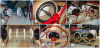
The solution implemented was based on intermediate polyamide discs supporting the transversal load and a grip system different for each of the axis. The front axis grip system was based on insufflate bicycle tires (Figure 7a). The back axis grip system needed higher stiffness and was based on lateral pressure discs (Figure 7b). A perspective of the set front + back supporting axes prepared to receive the winding coils and during operation is presented in Figure 7.
7.3 Substructure: clamping table for FSW
The table for clamping the sheets (and extension tabs) for FSW in a butt joint configuration was designed in according to the following requirements:
- Able to support the loads applied during the FSW;
- Total weld length of 1200 mm comprising the 1100 mm width of the sheet plus the 50 mm within the 2 extension tabs;
- To allow the sheets to run around it, after releasing the welded foils.
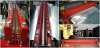
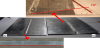
The material of the anvil was made of technically pure copper with dimensions: 1300 mm x 300 mm x 10 mm. This material avoided the adherence between the processed zone of the soft aluminium sheet and the anvil during the FSW. The final sub-structure of the table, represented in Figure 8, had high overall stiffness and reduced vibration.
8. Results
8.1 Selection of FSW process parameters from tensile tests
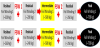
During the Task 1 the preliminary weldability tests done with the FSW Tool 1 (M3 probe) have shown good forging effect with relatively low loads but the amount of material viscoplastic flow is not enough to assure the good processing of the joint line with full and regular penetration. Thus, Tool 2 with a small tilt angle of 0.5 degrees was selected for final welds. Figure 9 depicts the results obtained for the tensile tests, where it is possible to conclude that Tool 1 presented a premature failure at the middle of the weld.
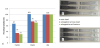
From the results of Figure 9, it is possible to verify that the FSW 2 set of parameters, presented in Table 4, resulted in no loos of mechanical strength of the weld specimens, which was established as the requirement number 3 for the properties of the foil winding coils welded by FSW. The loss of elongation is not significant (less than 30 %) and was not among the requirements because the real loading condition is static bending with no impact loads.
8.2 Visual analysis
All the face surfaces of the welds, i.e. the surface side in contact with the shoulder of the FSW tool, were analysed focusing regularity of striates and width of the weld bead. The root surface of the welds were analysed focusing the evidence of penetration level and regularity. Only perfect results, concerning these features, were accepted for all the welds implemented between the aluminium foils. An evidence of the benefit in applying the FSW to join these winding foils is the control of residual deformation. Figure 10 depicts the difference in angular distortion from applying the GTAW and FSW to the Task 1 welded samples with about 300 mm (length) x 100 mm (width).
Contrasting with the planar samples welded by FSW, the samples welded by GTAW present an angular distortion of about 13o (Figure 10c). The low distortion level of the FSW welds are in according to the requirement number 2 for the properties of the foil winding coils welded by FSW.
8.3 Micro-Hardness
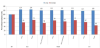
The hardness distribution of the welded coils is presented in Figure 11.
The results show that the processed zone undergoes a hardness increase of about 60 % from the original 27.9 HV02, of the base material, to about 45 HV02. This fact justifies the reason why in specimens from sound FSW beads the fracture during tensile tests does not occur in the processed zone but well inside the base material. Thus, it is possible to conclude that the processed zone by FSW shields the weld bead from fracture under tensile loading.
8.4 Bending tests
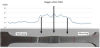
The mechanical resistance of the welded specimens under bending load is present in Figure 12. This test is one of the highest demanding for FSW specimens. In fact, any lack of complete penetration, one of the most prone to happen defects in conventional FSW, is easily exposed under this type of loading. The Figure 12 presents results for specimens extracted from the start zone, middle zone and end zone of the 1100 mm long weld bead. In the middle section, results are also presented for smoothed face surface and root surface, to investigate eventual benefit in post-weld grinding any of the welded surfaces.
From the results of Figure 12, it is possible to verify a benefit of about 20% relatively to base material in terms of maximum bending that the welded coils are able to support. This result overcome the minimum condition established as the requirement number 3 for the properties of the foil winding coils welded by FSW. The elongation at maximum bending load is reduced from base material properties. The results in the three different zones are similar. In addition, the results for face surface in tensile and root surface in tensile are similar for all the welded zones. There is no evident benefit in polishing any of the weld surfaces (face or root surface). This result means that the maximum productivity condition corresponds to the maximum mechanical resistance reached.
8.5 Metallographic analysis
The Figure 13 depicts some of the metallurgical features of the FSW bead.
In the macrograph (2.5x) it is possible to distinct the thermomechanically affected zone (TMAZ) with the central dynamically recrystallized small grain sub-zone, the nugget, as characterized by Vilaça et al. [15]. The TMAZ different properties were distinguishable in the hardness test (Figure 11). The zone adjacent to the TMAZ corresponds to the heat affected zone (HAZ). The distinct small grain size and thermomechanical processing energy accumulated within the TMAZ zone is the origin of the mechanical strength matching in tensile load tests and overmatching in bending load tests.
8.6 Electrical conductivity
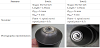
The laboratorial apparatus applied during the analysis of the local electrical conductivity on the vicinity of the FSW processed zone is present in Figure14.

The results express the very low impact of the FSW weld beads on the conductivity of the aluminium winding coils. The decay from the base material electrical conductivity (63.7 % IACS) is less than 4 %. The reduction is due to the substantial reduction of the grain size inside the TMAZ of the weld bead as concluded by Santos et al. [16]. The small loss of conductivity in the weld zone is within the limits established in the requirement number 4 for the properties of the foil winding coils welded by FSW.
9. Conclusion
The most significant observations from the present study are the following:
- An alternative method for welding aluminium foil winding coils was developed and successfully implemented.
- It was shown that it is technologically feasible to join by FSW, and rewind, residual winding foils producing new long coils along the full width and with low distortion, and similar mechanical resistance and electrical properties to the original ones. I.e. fulfilling all the four requirements established for the properties of the foil winding coils join by FSW.
- A dedicated structural system was designed, produced and implemented for guiding the base materials into the weld zone during the feeding period, clamping the sheets during the weld period and rewinding the coils immediately after the weld.
- The maximum load capacity of the welded zone matches the base material properties for the tensile tests and overmatches in about 20 % for the bending tests. Nevertheless, the ductility of the weld zone is reduced.
- The residual deformation of the foil winding coils welded by FSW is within the strict requirements to be admissible, and not relevant when compared with other alternative welding processes, e.g., the GTAW.
- The metallographic features of the weld bead present the typical sub-zones of the volume affected by the FSW processing, with a significant reduction of grain size in the TMAZ and mainly in the nugget.
- The hardness of the welded zone is increased by about 60 %, i.e., from the original 28 HV02 of the base material to 45 HV02 along the TMAZ of the weld bead. This has shown to shield the weld zone from any facture for the best set of FSW parameters.
- The electrical conductivity in the weld is reduced less than 4 %. Thus, the effect of the thermo-mechanical processing by the FSW process is not significant envisaging the final application of the new welded foil winding coils.
- The use of the anvil made of technically pure copper enabled the application of FSW to these soft aluminium components without adhesion of the root of the joint to the anvil as happens with the anvils made of steel.
Competing Interests
The authors declare that they have no competing interests.
Acknowledgments
The authors want to acknowledge the support of SIEMENS, S.A., Energy Sector - Transformer Factory FS – Sabugo, Portugal.