


1. Introduction
The comfort and safety of driving a vehicle mainly depend on the good working states and the symbiosis between the components of the vehicle suspension system. A suspension system of any vehicle is composed of a shock absorber, a spring and most importantly a tire. The main objective of this trio is to isolate the occupants of the vehicle from any external disturbances caused by interaction with a roughened ground while permitting the driver to keep an efficient and safe control on his vehicle. If any one of these components is badly designed, manufactured, mounted or used, severe consequences could disturb the ride comfort of people inside the vehicle and even jeopardize their safety. As vehicles have become more robust, reliable and sophisticated, drivers became less aware of the importance of their tires. Tires have significantly improved in terms of safety, performance and wear, but they still need more attention than most of the car components.
There are many factors that can result in a tire failure (puncture or blowout) or increase its probability. Such an unpleasant event can happen at any time when a tire loses suddenly or gradually its internal air pressure. This pressure drop prevents the tire from accomplishing its principal task; that is to support the weight of the vehicle and thus, make the driver fail to maintain a straight and safe trajectory which leads very frequently to a harmful car accident.
A lot of car accidents due to tire failure are being recorded annually. These accidents involve either injuries or fatalities and thus should be taken seriously. The National Highway Traffic Safety Administration (NHTSA) estimates that tire failures play a role in causing about 11,000 traffic accidents each year in the U.S, and almost 200 people die in those crashes [1]. Similarly, road casualty data in the UK reveal that defective tires were responsible for more than 1,210 road casualties in Great Britain during 2010 [2]. In the period between 2006 and 2010, the total number of tire-related deaths on UK roads exceeded 160. Moreover, in the UK during 2012/13, around 7.7% of cars, 3.8% of large passenger vehicles, and 7.2% of goods vehicles failed the ministry of transport test because of faulty tires [3].
A tire is a product of complex engineered composites. It consists mainly of a reinforced rubber toroid mounted on a metallic rim. The air trapped inside creates an inflation pressure that is responsible for carrying the load, transmitting forces, absorbing shock, providing grip and resisting wear. In a tire, there are multitudes of components and rubber formulations. For reinforcement, tires also have several types of fabric and several kinds and sizes of steel. Some of the steel are twisted or braided into strong cables. On the external shell, the tread provides the required friction with the road surface and gives better traction. The purpose of the patterns on the tread is to facilitate the evacuation of water and optimize the wear rate. Compared to a rigid wheel, the conventional air-filled tire has numerous advantages: good radial elasticity, better grip with the road, and a low mass. On the other hand, the air tire has also many weak points: mainly its vulnerability to unsteadiness of air pressure. The variation of air pressure affects the performance of the tire and considerably modifies the ride comfort of passengers. Among all possible threats, the risk of a blowout on the road is certainly the most dangerous one. In addition to its complex structure, even the computational modeling, and analysis of a pneumatic tire is a difficult and challenging task too. The main complication is due to the presence of constraints such as nonlinear material, nonlinear geometric conditions, and nonlinear contact boundary conditions.
Since the beginning of the twentieth century, several attempts have been made to develop flat-proof non-pneumatic tires (NPT) based on flexible elastomer layers or deformable spokes that could provide the same mechanical properties of the air trapped inside the tire [4-6]. In the early 1970s, the NASA’s Lunar Roving Vehicle was the first serious project where airless tires were used. To provide the required traction on the dusty moon surface, the 9x32-inch tires consisted of V-shaped titanium treads wrapped around steel-mesh toroids and attached to aluminum wheels [7]. With the new technology of airless tires, there is no need for periodic maintenance to refill the tires with air and maintain an appropriate internal pressure. Such principle eliminates the worry of punctures and enhances considerably the safety of the vehicle.
Since the recent emergence of newly invented non-pneumatic tires (NPTs), the most common concept was the use of an elastomer layer with reinforced rings and a distinctive structure of spokes, anchored to the inner side of the tire and uniformly distributed around the rim. The set of spokes support the weight of the vehicle and deform to provide the cushioning effect exactly like air pressure tire [8-10]. Research on NPTs hasbeen actively conducted to improve structural performance; e.g., contact pressure [11], design and structure of flexiblespokes [12] and rolling resistance [13]. To cope with the growing demand for safer tires, the concept of flat-proof airless tires was brought back home to the tires market by several companies. Due to their particular non-hazardous behavior and to their good stability, innovative designs such as those proposed by Bridgestone [8] and Michelin [9] had already gained the attention of researchers for particular use in military and space mission’s applications. In both solutions, the air of pneumatic tires (PT) was replaced by series of flexible polygon spokes that undergo millions of tension–compression cycles while the tire is rolling.
In particular, the model developed by Michelin called the “Tweel” and classified by Time magazine as “one of the 2005’s most amazing inventions” was claimed by the Michelin to possess three-timeslonger tread life and five-times-higher lateral stiffness, compared to conventional PT, with only a slight increase in rolling resistance. For this model, and all other spokes-based models, the main concern remain an optimum geometry design and a good material selection which ensure an efficient resistance to the highly disturbing tensioncompression cyclic fatigue load, especially in the critical spots with sharp geometrical entities usually more vulnerable to high-stress concentration levels.
Recently, flexible honeycomb solution with different shapes, made of polyurethane (PU) has been proposed as a new alternative for NPT spokes, to be used in applications that require high deformation [14]. It was found that having both resilience and stiffness while relying exclusively on material properties is impossible. Types and geometries of the cells are the key factors in determining the in-plane flexibility of hexagonal honeycombs under uniaxial loading.
2. Discrete Spokes Designs
So far, one of the most common solutions for the non-pneumatic tires is the replacement of the air trapped inside the toroidal volume around the rim by the use of discrete spokes, equally distributed in the radial plan, between the inner and the outer rings. In such designs, the spokes play the role of elastic elements which deform or bend according to the amount of load applied in the radial direction and hence deliver the required stiffness. For the majority of existing solutions the main problems are the limitation of the ride quality (directly related to the number of spokes), the restricted resistance to fatigue in the zones of stress concentrations, the vulnerability to trapping debris which may create unbalance and possibility of sound emission due to spokes vibrations and to air circulation through the open lateral surfaces.
To investigate the effect of discrete spokes on the wheel performance, a finite-elements analysis using a commercial finite elements code (Solid Works) has been achieved on different models of spokes-based airless tires (Figure 1). The dimensions of the NPT were selected to be the same as a normal PT. The spokes thickness was set to 5 mm in all models for the sake of comparison with the literature [15].

The analysis made for model A, as an example, involved the change in spokes number and its effect on the radial stiffness at different angular positions. The value of stiffness was not the main concern of this study but rather how uniform it is with respect to the angle value between two consecutive spokes. For each angular position between two consecutive spokes, a radial force was applied, the deformation at the same point was recorded and the radial stiffness was computed. Figure 2 depict the stiffness variation, normalized relatively to the average value (in unit-less form), with respect to the angular orientation. One can see that the radial stiffness is a periodic function of the angular position of two consecutive spokes. The shape of the function and its periodicity are mainly related to the number of spokes and to their individual geometries.
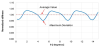
Several numerical simulations have been achieved for a number of spokes varying between 10 and 80. For each case, the maximum stiffness variation was recorded and then normalized relatively to the average stiffness value. The final results of maximum stiffness variation expressed in percentage, are displayed in Figure 3, with respect to the number of spokes.
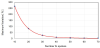
As expected beforehand, the increase of the number of spokes flattens the stiffness variation curve and decreases considerably the fluctuations amplitude towards the average value. The immediate result of that would be a ride with smoother quality. Based on this simulation results, we can state that any optimum design of airless tire using discrete radial spokes as main solution to replace the effect of air in pneumatic tires, can’t provide the desired degree of ride comfort unless it has a high number of spokes between the inner and the outer rings, which deliver a minimum level of stiffness irregularities (an infinite number of spokes would be the ideal case!). Therefore, a modified design based on the continuous distribution of springs would be the optimum solution for such a problem. One possible way to achieve this concept would be by integrating the spring effect in the lateral plan (main elastic behavior will be embedded in the side walls) (Figure 4 and Figure 5).

3. Continuous Spokes Design
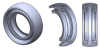
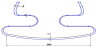
Unlike discrete spokes solution, the continuous stiffness design is not affected by the angle of rotation of the tire, which is the main advantage that makes this type of tires the most suitable in terms of ride comfort. The chronological metamorphosis of the cross-section is depicted in Figure 4. The design process started from a basic toroidal shell similar to a donut inflated with air. Then, the cross section shape has been modified several times, from an ordinaryclosed circle, to an open circle (more convenient for mounting and dismounting),to a more complicated contour with more design parameters that may facilitate the later optimization/matching process between the mechanical properties of the old PT and the new NPT.
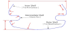
For the final design, the tire shell is divided into three portions:
- The outer shell which provides the tire-road contact
- The intermediate shell which provides the elasticity
- The inner shell which provides the tire-rim contact
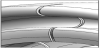
To reduce the stress concentration in the intersecting curves, which may restrict the maximum allowable deflections; all the sharp angles have been curved. Details of the cross section are depicted in Figure 5.
The new tire should be designed to fit exactly with the conventional pneumatic one, in terms of dimensions and mechanical properties (mainly radial stiffness). The final design, with a constant overall thickness of 7 mm, is shown in Figure 6.
4. Experimental Investigation of Pneumatic Tires
One of the main concerns in the development of any new NPtire is to ensure itsperfect interchangeabilitywith other classical tires of similar sizes. Independently of their types, all tires mounted on the same vehicle, should provide the same radial stiffness and consequently the same level of ride comfort. To ensure such matching, it is important to start the experimental investigation by assessing the mechanical properties (radial stiffness) of different brands of pneumatic tires under compressive loads.
5. Experimental Setup
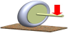
In order to generate the same loading conditions on the tire as if it was mounted on the car, a special fork-shaft system was developed for the experiment (Figure 7).
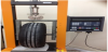
The test was done on different well-known brands of tires, manufactured in different countries, but all having the same specifications of radius and size ratio (Rim Size = 15”, Width = 8”, Aspect Ratio 65%). The five brands were randomly coded as A, B, C, D and E in this study.
Different air pressure values ranging from (1.6 bars to 2.4 bars / 23 psi to35 psi) were used to study the effect of the air pressure on the tires stiffness. For each pressure, the experiment was repeated three times and the pressure was measured using different pressure gauges.
6. Experimental Results – Tire Load Capacity
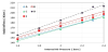
The variation of radial stiffness with respect to internal air pressure, for all five brands, is represented in Figure8. As could be seen from displayed results, the PT stiffness is related to the internal air pressure through a linear relationship of the form:
Where
Kt is the tire stiffness,
Kc is the carcass stiffness,
pi is the inflation pressure,
Kp is the inflation pressure dependence modulus
This linear behavior is in perfect agreement with the finding of Lines and Murphy [16]. However, one can see that the different brands of tires have different stiffness values. The carcass stiffness is the highest for sample D and the lowest for sample C.
The correct tire pressure is a very important factor for getting good gas mileage and maximum life span. Such parameter is usually specific for each brand. However, for most passenger cars, the recommend pressure value is usually set between 2 and 2.4 bars (29 and 35 psi) when the tire is cold [17]. Because of that, and according to the previous graph, the radial stiffness of the NP tire to be manufactured should range between 170 and 210 N/mm Figure 8.
7. Manufacturing and Testing of the Non-Pneumatic Tire
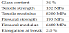
Now that the cross shape geometry has been selected and the design target specified, a prototype could be manufactured. However, a convenient choice of material is required beforehand. To seek a proof of concept, Fiber Reinforced Polymer (FRP) has been chosen to manufacture the first prototype of NP-tire. This type of composite is easy to shape, has excellent damping properties with light weight and can be used in multitudes of environments without having any particular concern in utilization. The fatigue behavior of FRP varies from one type to the other, but evidence of their use in fatigue loading for several vehicle components has been reported in the literature [18]. As for the first prototype, FRP with only random fiberglass will be used.This type of material, with properties displayed in Table 1, is cheap and available. The random orientation of the fibers provides almost an isotropic behavior. Further optimization of the fibers orientations and the number of layers could be done later, once the full loading behavior is understood.
[Cure of 24 hours at 20oC and 16 hours at 40oC].
In order to check the expected stiffness of the designed tire and to verify its matching with the previous experimental results collected from the conventional PT, a Finite Element simulation using a commercial finite elements code (Solid Works) was accomplished (Figure 9). Contrarily to a real situation where the vehicle’s load is applied to the middle of the tire, through a circular contact with the rim, while the lower part is bounded to the ground (Figure 10), the tire was considered in an upside-down position, where the load coming from the contact with the flat surface (representing the ground) is applied on the top. The internal surface was set as fixed to simulate a full contact condition with the metallic rim.
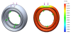
(a) Boundary Conditions. (b) Vertical deformation.
The FEA results show that, under a load of 5000 N (quarter of vehicle weight of 2000-kg), the maximum radial deflection of the tire is 1.798 mm, corresponding to a radial stiffness of:
This value of stiffness is very high compared to the ones measured
on different conventional pneumatic tires
To obtain comparable values of stiffness, the choices are limited:
- Design a tire with constant thickness but with different materials allocated to different spots, such as the one in the intermediate shell (responsible for providing the required elasticity) will be more resilient. Therefore, the problem will be oriented more toward material science investigation.
- Keep the same material for the entire tire, but use a more complex solution based on variable thickness design.
- By keeping the same material, the new tire design will have the following features (Figure 11):
- Thick outer shell,of 5mm thickness, in contact with the ground,
- Thin elastic shell, of 2mm thickness, at the middle hollow channel,
- Thick inner shell, of 5mm thickness, in contact with the rim. Such increase of thickness at this particular location does not contribute to the radial stiffness of the tire. It is only brought to ensure a good lateral stiffness during the cornering maneuver.
A new model of the NP-tire with geometric properties as specified previously has been investigated again by using FE method. The simulation results reveal a maximum vertical deflection of 2.056 mm under a load of 5000 N, which corresponds to an equivalent radial stiffness of 2432 N/mm. This new value is less than the previous one but still far beyond the fixed target. In some way, the obtained results were unexpected but certainly not strange. Indeed, inflated tires, having a toroidal shape, are characterized by a non-developable surface with a double curvature that makes the structure stiffer than a regular flat shell. It is mainly for this reason that in Figure 10, the overall deformation of the tire is confined more to the top of the tire (near the loading zone) instead of the sidewall which is designed to provide the required elasticity in the tire. To solve this issue, and allow both the stress and the deformation to reach the elastic part of the tire, located in the sidewall, the circular integrity of the tire should be broken. One possible way to do it is by introducing a set of tiny cuts in the sides of the tire (Figure 12).
The final design (third prototype) is represented in Figure13. It contains 10 cuts equally distributed around the tire with holes drilled at each end to prevent cracks propagation from these spots.

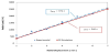
In order to check the tire load capacity provided by this final design, both FE simulation and experimental investigation were accomplished. The obtained results are displayed in Figure 14 and show a good agreement between the simulation and the real measurements. Even though the final value of radial stiffness (372 N/ mm) is not equal to the desired target (which is around 200 N/mm), but the results are close to each other more than ever before.
8. On-Road Testing
Whenever automobiles are equipped with new accessories, particularly new tires, they require on-road testing to investigate the efficiency of the added element and to assess the overall performance of the entire vehicle. The field test that we conducted aimed to collect real data that will aid in determining the shock and vibration characteristics of the vehicle with both conventional pneumatic (P) and airless (NP) tires. The new tire was supposed to be mounted on a very particular metallic rim, specially designed for it, to allow its easy mounting and dismounting. However, for time and manufacturing constraints, it was finally mounted (with a substantial difficulty caused by the high stiffness of the NPT) on a regular PT rim. The new tire was wrapped all around with a thick layer of rubber and the entire wheel was mounted on the rear-right side of a “Honda Accord 2007”.
The on-road testing consisted in moving straight at a constant speed of 20km/h and then rolling over a speed hump (Figure 15). For recording the vehicle response characteristics a “Dytran 7543A USB Digital” tri-axial accelerometer was installed on the outside frame of the vehicle and used to collect the response. The data acquisition and post processing calculations (FFT) was performed by the “VibraScout™” Software.

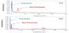
Figure 16 indicates the frequency response of the vehicle when equipped with both types of tires (PT and NPT).
9. Conclusions and Future Work
The catastrophic failure of a tire is a frequent, dangerous and unexpected event that may lead to a tragic accident which could induce injuries or even fatalities. Therefore, the main objective of this project was to develop a new generation of airless tires with a higher level of safety that prevents any chance of being punctured or becoming pressure-less while being used. The new NPT should be designed to be lighter, cheaper, and more reliable than the current pneumatic tires but still provide the same mechanical properties and the same ride comfort.
The development process started firstly by numerous experimental investigations to assess the load capacity and the radial stiffness of five different brands among the most known and reputable of conventional pneumatic tires. In a second step, a finite-elements numerical investigation was conducted on some of the existing spokes-based NPT,to study the effect of spokes distribution on the steadiness of their stiffness properties and the quality of their ride comfort.
An innovative design of non-pneumatic tire was developed based on the findings of numerical and experimental investigations made previously. The proposed concept was based on the simple idea of adding a curved geometry to the sidewalls in order to create a flexible zone that could provide the same elasticity as in a conventional tire. A finite-elements investigation was carefully conducted to optimize the cross-section shape geometry of the new design and to match its mechanical properties (load carrying capacity and radial stiffness) with the values obtained earlier from commercial pneumatic tires. For the sake of proof of concept and to demonstrate the feasibility of the solution, a suitable material (based on Fiber Reinforced Polymer with random orientation), known for its easiness in shaping and manufacturing, was selected and used to build the first prototype.
Both FE analysis and practical experimental testing showed that, for this type of material, the desired stiffness cannot be reached with a continuously revolved profile. To solve this issue, cuts were introduced to break the integrity of the circle and to increase the resilience of the tire. The final product was a non-pneumatic tire with mechanical property (radial stiffness) very close to most of the commercial pneumatic tires.
The design of the new non-pneumatic tire can be improved further. A fundamental part of such improvement would be through an appropriate choice of the material. A good combination of the material and the geometry would let the NP tire safer, provide optimum ride comfort and with stand the lateral forces that arise during steering and cornering. Extra analysis is also required to investigate the dynamic behavior of the tire. A multitude of tests on acoustics, vibration, reliability and endurance of the tire, both on the road and off the road, are required before such product could be claimed to be convenient and safe for large-scale public use.
Competing Interests
The authors declare that they have no competing interests.
Acknowledgments
The author would like to express his gratitude towards his students (Mohamed Ebrahemi, Musab Al Mozien, and Yousef El Hadary) for their kind co-operation in conducting the experimental investigation.
Abbreviations