


1. Introduction
Heating and cooling loads renders a significant part of the world’s total energy demand. Particularly, 40% of the final energy consumption in the European Union (EU) is for the building sector with space heating representing 68% of the total household consumption, followed by water heating at 12% in 2009 [1]. For an environmental friendly strategy the reduction of CO2 emissions and promotion of the use of renewable sources, the EU passed the Directive 2009/28/ EC [2] which implied that the member states have to increase the utilization of renewable energy sources as well as energy efficiency and savings by 20% until 2020. Also, a further 80% reduction in the energy consumption of the existing buildings, relative to the 2010 levels by 2050, was passed in the European Parliament (March 2013).
More specifically, the specific heating consumption for typical buildings varies from 15 kWh/m2 yr to 100 kWh/m2yr [3-4]. In order to cover this load, many technologies are used and for this reason this research field has rapidly been developed. Solar energy utilization is very beneficial because of the zero operating cost and is able to cover high loads in countries with high radiation level as Greece. The last years increase in fossil fuel price and in the electricity cost, combined with the new life-style, creates greater need of space heating which leads to higher yearly costs. Therefore, new and innovative ways are applied in order to reduce this cost and to make heating cost friendly to people. Solar energy utilization for space heating consists an efficient way to cover the building needs or a part of them. Especially for Greece with a high yearly radiation level of about 1400kWh/m2 to 1800kWh/m2 [5], the solar energy use can contribute in solving the energy problem. Athens with a yearly radiation level of 1587 kWh/ m2 [6] is the most populated city and so it is the most representative city for studies which are related to buildings. At the same time, under floor heating systems are a heating technology which is used with an increasing rate because of the more satisfying indoor micro-climate conditions to the occupants [7]. The first steps of this technology were in Germany in the decade of 1970 in data centers and in commercial buildings [8-9]. Nowadays, the 50% of the new constructed European buildings use this technology [10] because underfloor heating systems reduce the seasonal heating about 18% [11] and improve the thermal comfort conditions inside the buildings [12].
Many studies have been conducted in this sector. Alajmi and El- Amer [13] developed an under floor-air-distribution system and concluded that this system saves energy compared to ceiling-based air distribution. Moreover, other studies recite the advantages of under floor heating systems in thermal comfort conditions [14-16]. Zhai et al. [17] examined and tested the design and performance of under- floor heating system with solar energy for a typical building. Badran and Hamdan [18] studied theoretically and experimentally an under- floor heating system using solar collectors and solar pond and proved that the system with solar collector is 7% more efficient than the solar pond system. In other studies, Athienitis [19] create a numerical model to predict the underfloor heating load under high solar gain and concluded that controllers should be used in order the floor temperature does not exceed the comfort limits. Also, Al- Khalayleh et al. [20] in a theoretical analysis of an underfloor heating system driven by solar collectors showed that solar energy is able to cover the heating load sufficiently. Finaly, the combination of underfloor heating and solar energy as heat source has been analyzed for a large building with a high specific heating load of 18kWh/m2 year [21]. According to bibliography [22], the main programs which have been used for solar system simulations are TRNSYS, ESP-r, Insel and Energy Plus with TRNSYS used in the majority of the cases.
It is known that a comfortable environment is essential for health, but also for the productivity of the building's occupants [23-24]. Other studies have proved that people spend a great part of their time inside buildings, so to work, to live or to sleep [25-26]. Moreover, many countries use a combination of policy regulations to create more efficient buildings, but in many cases the results are not the desirable. For instance, in many countries, the energy requirements for buildings suitable for funding are not aligned with the proper energy requirements of the buildings [27]. Higher energy prices (including energy taxes) increase the profitability of energy efficiency investments. However, studies in several countries have shown that the consumer response in the buildings sector, to higher energy prices, is relatively inelastic. More specifically, a 1% increase in household energy prices would lead to a reduction in the energy demand of 0.25% [27]. One of the most easy and efficient methods to decrease the transmission rate of heat and energy consumption to heat buildings is the utilization of appropriated thermal insulation in the building envelope [28]. Architectural and physical properties of buildings, such as thermal mass, structural material, and its shape, are the most important parameters that influence the space-cooling load. During the last few decades, utilization of insulation materials has increased significantly, because of the increasing values of insulation thickness imposed by national regulations [29]. An optimum thickness of insulation offers minimum total cost, including the cost of insulation and energy consumption on the life of the building [28].
In this study, the impact of the insulation layer in the performance of two solar heating systems is analyzed. More specifically an underfloor solar heating system and a solar driven fan coil system are compared energetically and financially. The optimum case is the one with the lower cost, by taking into consideration the thickness of insulation layer. Moreover the maximization of solar coverage is an extra goal of the simulations in order to create an environmental friendly system. The Greek high solar potential combined with the low heating loads of Athens, the city of this study case, are factors which makes solar heating systems to operate efficiently. The simulation tool is the commercial software TRNSYS, which gives many features to the user for dynamic simulations for a great time period.
2. Theoretical Basis and Methodology
2.1 Building structure
The structure of every building is a determining factor for the heating loads. More specifically, the thermal resistance of the walls and the roof specifies the heat exchange between the building and the ambient. Equation 1 presents the way that this parameter is calculated for a typical wall structure.
Usually in building applications, the thermal transmittance U is used, which is calculated from thermal resistance, as equation 2 presents:
This parameter is influenced by the material and their thickness. Insulation layer is the most important parameter in the thermal transmittance of structural component. For this reason, the analysis of the impact of the insulation layer thickness on the heating loads has a significant value. Another important parameter with high impact on the thermal behavior of the buildings is its thermal mass. This quantity is determined in equation 3.
M is the total number of structural components (walls, roof and ground) and Ni the total number of layers of every component. Ai is the wall area without windows; because in this analysis the thermal mass of glasses is neglected.
2.2 Solar collector’s efficiency
Solar energy utilization is a deciding factor for improving the environmental status of buildings. Especially in heating applications, solar collectors perform ideally. The most mature technology for household applications is flat plate collectors (FPC) which combines high efficiency with a low cost. Equation 4 presents their efficiency by the direct way:
, where Ac is the collecting area, GT the solar radiation on titled surface and Qu is the useful energy gain. The calculation of useful energy is presented in equation 5:
In many simulations and studies, the efficiency of the FPC is calculated according a general formula which presented in equation 6.
The first term of equation 6 is related to the optical losses of the collector, while the second to the thermal losses. This efficiency is approximately linearly with the quantity (Tin-Tam)/GT, for usual applications as the heating of this study.
Solar energy potential is high for Greece, but in many cases is not enough to cover the full load of the applications. Thus, auxiliary energy is needed in order to complete the thermal energy demand. A useful parameter in solar applications is solar coverage which shows the ratio of solar energy utilization in the total demand, according equation 7.
2.3 Financial evaluation
The modern design demands energetic optimization combined to financially sustainable solutions. Thus, financial evaluation of every technology is needed in order to predict which one is the most feasible in reality. The basic criterion of evaluation two heating technologies is the net present value (NPV) in order to calculate the total cost during the project life. Equation 8 presents the simplest form of this economic parameter.
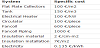
The first temp C0 renders the capital cost of the examined investment and the second present the operating cost. N is the project life, C1 is the specific operating cost and Qaux the auxiliary consumed energy. In building applications, electricity is used as the supplementary heat source in order to respond rapidly. It is important to be mentioned that the increase in electricity cost is equal to the discount factor, which is a realistic assumption of the financial evaluation. The main specific cost of the examined devices and systems of this study, are presented in table 1 [30-31].
2.4 Methodology
Two different solar heating systems are analyzed energetically and financially in order to predict the optimum one. Simultaneously, the impact of insulation layer is taken into consideration because of its high influence on the heating loads. The cost of the insulation is also calculated in the financial evaluation because it is able to increase the total cost of the investment. The insulation layer ranges from 2cm to 10cm, in order to cover all the typical values for usual buildings. It is important to state that the insulation layer of the external walls and of the roof are changes together in the parametric analysis.
In the solar heating systems, the collecting area and the storage tank volume are the main parameters that have to be optimized in every case. The impact of tank volume is small but it has to be greater than a minimum value in order to supply satisfying hot water quantity to the system.
3. Examined Systems
3.1 Examined building
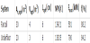
The examined building of this study is a typical Greek building with usual structural materials. Athens (Φ=38°)is the city where the building is located and is characterized by high radiation level annually. The examined building consists of 4 same external walls and a roof. Windows are placed in East, South and Western direction in order to utilize the solar radiation in a high rate. Table 2 presents the main parameters of the examined building.
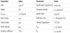
It is important to be stated that the windows are double in order to reduce the thermal losses and their U value in table 2 has taken into consideration the window frame. The walls have 5 layers. The insulation layer changes from case to case because this quantity is analyzed parametrically. More specifically, the outer layer is plaster with 1.5cm thickness, the next layer is a 12cm brick, insulation follows with a varying thickness from 2cm to 10cm, another 12cm brick follows and the inner layer is plaster of 1.5cm. Roof consists of a cement layer of 20cm, an insulation layer which also varies from 2cm to 10cm and an inner plaster layer of 1.5cm thickness. The building ground has various layers of cement and insulation. In the first case their structure is simple but in the second there is the underfloor heating system inside it. In order to make a realistic comparison, the U-value was the same in both cases and equal to 0.317 W/m2K. The properties of the structural materials are presented in table 3.
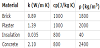
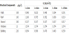
The most crucial parameter from the above table is the heat conductivity of insulation which determines the U-value of every structural component in a high rate. The next table presents the thermal transmittance of every structural component and the total equivalent of the whole building. The results are presented for insulation thickness from 2cm to 10cm with step 2cm.
By taking into consideration the KENAK regulations for Greek buildings, the equivalent building thermal transmittance has a maximum acceptable value. The ratio of external building area to the building volume is 1.07, greater than 1, fact that leads to a needed mean thermal transmittance of 0.73 W/m2K. This value is taken from KENAK tables [32], for climatic Zone B, where Athens belongs. By analyzing table 4, the insulation layer should be greater or equal to 4cm in order to satisfy this regulation. Another important parameter of the building is its thermal mass which calculated to be 156MJ/K and is approximately constant for all cases.
For thermal comfort conditions, the daily temperature should be greater than 22°C which means that a control system is used to determine the operation of the heating system.
3.2 Solar heating system with fan coils
The first examined heating system utilizes solar radiation with flat plat collectors and fan coils. More specifically, fan coils inside the building uses the hot water from the storage tank in order to heat the indoor air. For a building of 100m2, 4 fan coils are able to keep the thermal comfort conditions at preferable levels. The examined system is presented in figure 1.
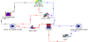
Water is the working fluid in the collector system and is warmed up from the captured solar energy. A storage tank is placed in the installation for storing the extra solar energy. This tank is modeled with 5 mix zones and losses heat to the ambient. An extra heater operates when the water is not hot enough to drive the fan coil system. The fan coils heat the air at 30°C making it capable to carry out the heating load. The control system is a thermostat which regulates the heating system operation. More specifically, when the indoor temperature goes under 22°C, then the heating system starts operating. Table 5 resents the parameters of the system.
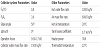
The left part of table 5 presents the characteristics of solar collector system. The collector is selective with low heat loss coefficient and is titled at 50° because the system is designed for winter operation. More specifically, the collectors perform better when the solar radiation is vertical to them, so the low position of the sun in the winter needs the collectors to be stand up. Moreover, the collector field is turned to the south direction which leads to optimum performance (azimuth angle equals to 0°). Their operation is adjusted for 8 hours per day, during the blighting hours.
The auxiliary heater power was set at 7kW, which is great enough to cover the loads of the examined building. The flow rates are presented in table 5 and have been selected after tests with the simulation tool.
3.3 Underfloor heating system with solar collectors
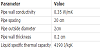
The next examined system utilizes the same solar collectors in an underfloor heating system. A piping system is located inside the ground of the building, especially in the cement layer. Hot water enters to this system and heats the ground, which heats the indoor air after a time period. The water lets the system with a temperature decrease of about 5 to 7 K. The maximum operating temperature of the underfloor piping is about 45°C, because a greater temperature is able to destroy the whole system. The total system is presented in figure 2.
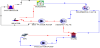
Figure 2 presents the system which includes the solar collectors, the storage tank, the auxiliary heater, the control system and the Building. The solar collector system parameters are mentioned in table 6 and are the same with them in the other examined heating system. The hot water from collectors stored in the tank in order to save water for hours without solar radiation. An auxiliary heater increases the water temperature over 40°C, when there is need. More specifically, the auxiliary heater operates when the hot water is not hot enough and when the indoor temperature is lower than 21°C. In other words, there is a second thermostat which determines the operation of auxiliary heater. By this way, the energy consumption is diminished a lot by keeping the indoor temperature in acceptance levels. It is important to state that two mixing valves are located in the return of the cold water from the underfloor system. By this way, the temperature of tank hot water is decreased and is able to be kept under 45°C by giving safety to the system. Table 6 presents the parameters of the heating system.
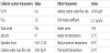
For the underfloor system, it is important to mention that the area is separated to 4 parts (segments). This is done automatically from TRNSYS by determining the minimum desired water flow rate in the system, which selected to be 1500 kg/hr. A four segmentations means that one double loop is located to 25m2, which is a satisfying design. Table 7 gives extra information about the piping of the underfloor system.
4. Results
4.1 Building loads
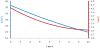
First of all, the heating loads of the building for the various examined cases are presented in this paragraph. The increase of insulation influences on the heating load by a great way, something which is obvious in figures 3 and 4. More specifically, figure 3 presents how the total heating load of the winter period changes with the insulation thickness.
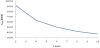
It is obvious that the increase in insulation thickness is able to decrease the heating load up to 3 times. Figure 4 presents the monthly distribution of the heating loads for various insulation layers.
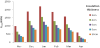
The maximum heating load is observed in January, with December and February to have respective heating loads. The case with 2cm insulation thickness is characterized by great loads and while the thickness is getting lower, the loads are decreased with a lower rate. By this figure, an insulation layer of 6cm or 8cm is able to create a building with acceptable heating loads.
4.2 Energetic performance of solar heating systems
Two solar heating systems were investigated and analyzed in order to compare them and to predict the impact of insulation thickness in the building thermal behavior.
The solar heating system with fan coils was simulated for various combinations of insulation thicknesses and collecting areas. In every case, the optimum volume for storage tank was determined in order to have the sufficient water quantity for utilization. Table 8 presents the optimum storage tank volumes for every examined collecting area. It is important to state that the optimum tank volume was not influenced by the insulation thickness.
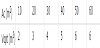
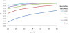
Figure 5 presents the yearly auxiliary energy consumption of the examined cases. It is obvious that a higher collecting area decreases the electricity consumption in the auxiliary heater. Moreover, a higher insulation thickness leads to lower heating loads, especially in lower collecting areas. After a critical collecting area of about 40m2, 6cm insulations are sufficient to minimize the auxiliary heater consumption.
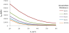
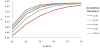
Figure 6 presents the solar coverage which is fully connected to the auxiliary heating consumption, according equation 7. It is clearly from this figure that for high collecting areas, the insulation thickness has lower impact in the loads and in the solar coverage.
The next examined system is the underfloor heating system. The same analysis is followed in this system in order to present its energetic performance. Table 9 presents the optimum volume of storage tank for various collecting areas.
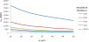
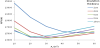
Figure 7 presents the auxiliary heater consumption and figure 8 the solar coverage. From these figures it is clear that a collecting area of 25m2 is able to cover the greater part of heating load. Insulation is very important and 6cm thickness is able to make the building energetically efficient. For collecting areas over 40m2, the impact of insulation is minimum because the available solar energy is able to carry out great heating loads.
4.3 Financial evaluation of solar heating systems
The next step of this study is the financial evaluation of these two technologies. The cost of solar collectors, of storage tank and of insulation is taken into consideration for the capital cost of every investment, while electricity consumption on the auxiliary heater is the operating cost of the analysis. The project life was selected to be 20 years which is close to the reality for solar heating systems. Figure 9 presents the Net Present Value of fan coil system for all cases. The goal is to predict the combination of collecting area and insulation thickness for minimizing the NPV. For each insulation layer thickness, there is a collecting area which minimizes the NPV. By comparing these local minimums, the total minimum is predicted. Figure 10 presents the optimum collecting area and the optimum storage tan volume for all the insulation layer cases.
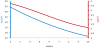
From figure 9 it is obvious that 6cm insulation with 30m2 of solar collectors is the optimum combination. The use of insulation layers of 4cm, 6cm and 8cm lead to feasible solutions. The use of 2cm is the worst case; because the heating loads are great and a great amount of money is spent for electricity consumption. Figure 10 shows that a greater insulation thickness demands lower collecting area for optimum financial performance. Moreover the respective tank volume is getting also lower for higher insulation thickness.
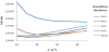
Figures 11 and 12 present the results for underfloor system. Net present value is minimum for 20m2 of FPC and 6cm insulation thickness, according figure 11. The case of 2cm insulation leads to unprofitable solutions, while insulation thicknesses of 4cm, 6cm and 8cm create sustainable systems. The greater examined insulation thickness of 10cm is not profitable because its impact of extra insulation thickness in heating loads is very small. From figure 12 it is obvious that the optimum collecting area and the optimum storage tank volume are lower while a greater insulation is placed in the structural components.
4.4 Final comparison of the two heating systems
After presenting the energetic and financial results of the simulations, the evaluation of them is the most important part of this analysis. Table 10 presents the parameters of the optimum cases of the two systems.
Fan coil system is the one with the lower NPV so this is selected as the optimum one. The optimum insulation thickness is 6cm for the two cases which is an important conclusion. The underfloor heating system demands lower collecting area but consume more auxiliary energy. The lower collecting area of the underfloor system is combined with a lower storage tank.
5. Conclusion
The impact of insulation thickness on the solar coverage of two solar heating systems is investigated in this study. The comparison is energetic and financial in order to be more multi-faceted. The final results show that 6cm of insulation is the optimum solution financially for the both systems. An important result is that the influence of insulation thickness on the solar coverage is getting low when the collecting area is great. This can be explained the high availability of solar energy in these cases.
Furthermore, the heating system with fan coils lead to a NPV of 13421€, while the underfloor system to a NPV of 13835€. These costs are close to each other with the one of fan coil system to be lower. Moreover, the underfloor system demands lower collecting area and lower storage tank for optimal operation, than the fan coil system. This is an advantage of this system. On the other hand, the auxiliary energy consumption is lower in the fan coil system something that makes this technology more environmental friendly. For these reasons, the use of fan coils driven by flat plate collectors is the most suitable solution financially and energetically.
Competing Interests
The authors have no competing interests with the work presented in this manuscript.
Nomenclature
A → Area (m2)
cp → Specific heat capacity (J/kgK)
C0 → Capital cost (€)
C1 → Operating cost (€/kWh)
E → Energy (kWh)
f → solar coverage
FR → heat removal factor
GT → Solar titled radiation (W/m2)
h → heat transfer coefficient (W/m2K)
k → thermal conduction (W/mK)
L → insulation thickness (cm)
m → mass flow rate(kg/s)
N → Project life (years)
NPV → Net Present Value (€)
Q → heat flux(W)
R → thermal resistance, (mK/W)
T → Temperature(°C)
t → layer thickness (cm)
TM → Thermal Mass (J/K)
U → thermal transmittance(W/m2K)
UL → collector losses coefficient(W/m2K)
V → storage tank volume(m3)
Greek Letters
η → efficiency
ρ → Density(kg/m3)
(τα) → transmittance–absorptance product
φ → Latitude (°)
Subscripts & Superscripts
amb → ambient
aux → auxiliary heater
c → collector
f,i → fluid inlet
f,o → fluid outlet
heat → heating
in → indoor
out → outdoor
u → useful