


1. Introduction
It is generally believed that underground structures have a strong seismic performance compared to surface structures because of the constrained effect of the surrounding ground [1]. Nevertheless, a number of underground structures have experienced significant damage during the 1995 Kobe earthquake, including subways, parking lots, tunnels and commercial streets. Most importantly, the strong earthquake caused the collapse of the Daikai Station, a reinforced concrete underground structure in the subway system in Kobe [2]. After few years, during the subsequent earthquakes, such as the Chi- Chi earthquake in Taiwan in September 1999 and Turkey earthquake in November 1999, a number of underground structures have also suffered severe damage, some quite extensively [3]. The damage provides sufficient evidence to suggest that the safety of underground structures in seismically active areas is still an important issue, but not well understood yet, or at least not well consider during design.
In this study, published researches on damage observation and analysis of the Daikai station are firstly reviewed and summarized. Based on the literature review, dynamic numerical analyses are conducted to investigate the damage mechanism of the Daikai station. The nonlinear dynamic behavior of the soil is approximated by the equivalent linear model. The Concrete Damaged Plasticity model is adopted to capture the damage evolution and progressive failure of the subway station under the strong earthquake. The dynamic explicit method (central difference method) is employed to solve the dynamic problem. The influence of the vertical motion on seismic responses of the station is evaluated and compared with that of the horizontal motion. Through the investigation, the goal of the paper is to determine, or at least estimate, the causes and the mechanisms of damage observed at the Daikai station, which would be beneficial for seismic design of underground structures in future.
2. Literature Review
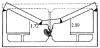
The Daikai Station, a cut-and-cover structure, was built between 1962 and 1964 [2]. It was located about 15 km from the epicenter of the strong Kobe earthquake. During the earthquake, more than 30 columns of the central section of the station completely collapsed, with the destruction position located at the connections between the top and bottom of the column and the slab. Total length of about 110m was completely destroyed [5]. Other structural components also suffered various damages, such as the concrete of the side walls were spalled, and the wide cracks led to obvious leakage [6]. The maximum subsidence of the national road above the subway was around 2.5m caused by the deformed top slab [5], as shown in Figure 1.
The collapse of the Daikai station was the first case of severe earthquake-induced damage to modern underground structure, and thus a number of researchers focused on the damage mechanism of the station in order to develop design theories and methods for practitioners. As observed from the damage of the Daikai station, the middle columns were the most seriously destroyed parts of the station. Thus, many researchers began to investigate the performance and failure mode of the middle columns. Yamato [7] conducted static analysis and considered nonlinear relationship between the moment and rotational angle at the end of the elements of the structure. It was concluded from the results that center columns failed due to the bending and shear failure of those columns. Based on the threedimensional finite element analysis, Samata [8] revealed that the shear failure of the middle column was prior to the flexural yielding of the slabs and walls. An et al. [9] observed from numerical results that the failure of the middle column was caused by its low shear capacity and poor ductility. Iwatate [10] summarized from shaking table tests of the scaled subway station that the scaled model collapsed due to lack of the load carrying capacity against shear at the middle column. Parra-Montesinos [11] predicted a reasonable range of drifts at which collapse was expected in the columns of the station by using the Elwood-Moehle column collapse model. Huan [12] developed a 3D shock isolator composed of dash spring and lead rubber beading for the middle column, and validated from 3D numerical results that the isolator could markedly reduce the deformation and damage of the column when fixed at the ends of the column.
What is more interesting is that, strong vertical seismic motions were recorded during the Kobe earthquake [13]. However, limited studies have investigated the effect of the vertical seismic motion on underground structures [14,15]. Iida [4] investigated that the damage of the station due to vertical force was still unclear. Chen [16] used the substructure subtraction method and considered the soils above the station as an affiliated structure of the station. It was concluded that the collapse of the columns of the Daikai station was induced by both the horizontal and vertical vibrations. Based on the pushover analysis, Liu [17] indicated that the strong horizontal and vertical seismic loads contributed to the failure of the subway station.
Other researchers investigated the damage mechanism of the Daikai station from different views. Sakai [18] found that the frequency components of an input motion lower than 2Hz had a strong influence on the relative displacement between the top and bottom slabs, and the effect of frequency components higher than 3Hz was negligible. Huo [19] investigated the load transfer mechanisms between the underground structure and the surrounding soil and found that the relative stiffness between the structure and the degraded surrounding ground and the frictional characteristics of the interface determined the response of the station. Nakamura [20] concluded that the damage of center columns depended on the stiffness of ground around the station. Uenishi [21] showed that a seismic wave with a specific frequency could induce resonance of a column at midspan of the station.
In general, great efforts have been made in investigating the failure mode and the collapse mechanism of the Daikai station based on a series of numerical and experimental approaches. However, a consensus on the collapse mechanism of the Daikai station has not been achieved yet. Moreover, only few investigations on the nonlinear seismic response of the station were addressed. As aforementioned before, the aim of the paper is therefore to fulfill these forward problems, that is, to determine the causes and the mechanisms of damage observed at the Daikai station after a series of nonlinear numerical simulations, as addressed below.
3. Numerical Model and Parameters
3.1 The dimension of the Daikai station
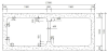
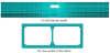
There were three sections for the Daikai station: the central section, the subway tunnels section and the access station section. The central section (see Figure 2), which was mainly damaged, was 17m wide and 7.17m high. The wall thickness was 0.70m. The thicknesses of the top and bottom slab were 0.80m and 0.85m, respectively. The top slab was located 4.8m below the ground surface. The middle columns had a rectangular cross section of 0.4m by 1.0m, spaced 3.5m between axes in the longitudinal direction.
3.2 Material model for concrete structure
As well known, concrete is a complex multiphase composite material. A number of constitutive models for the static and dynamic response of concrete have been proposed in the past [22,23]. The Concrete Damaged Plasticity (CDP) model [24] developed by Lubliner [25], Lee and Fenves [26], was used to describe the nonlinear behavior of concrete in this study. It uses two damage variables, the tensile damage factor dt and the compressive damage factor dc , to discount the elastic stiffness of concrete due to the increase of damage.
If E0 is the initial elastic stiffness of concrete, the stress-strain relations under uniaxial tension and compression loading are
Where σt and σc are the tensile and compressive stresses respectively, while εt and εc are the tensile and compressive strains respectively.
The plastic strain
Where
The plastic strain
Where
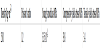
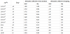
For the Daikai station, the design strength of the concrete was 23.52 MPa for the central columns and 20.58 MPa for other structural components, while the strength of the specimens for the central columns was 39.7 MPa [4]. Table 1 shows the parameters used in the CDP model.
3.3 Material model for soil
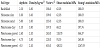
The ground surrounding the Daikai station is mainly composed of Quaternary Holocene sand and Pleistocene clay. The nonlinear dynamic behavior of the soil is approximated by the equivalent linear model. The parameters used in the model are referred to the test data from Seed [27], as illustrated in Table 2 and Table 3.
3.4 Boundary conditions and seismic inputs
The discretization of both the soil and the concrete structure is done with the eight-node hexahedral solid elements CPE4R, as shown in Figure 5. Perfect bonding is assumed between the subway station and the soil. The lateral boundaries are taken in the model as free boundaries. In the model the distance from the structure to the lateral boundary is more than ten times the dimensions of the structure. The adequacy of the type of boundary and mesh size was verified by running a number of preliminary numerical tests where the lateral boundaries of the discretization were placed at different distances from the subway structure. It was decided that the size of the discretization was acceptable when free-field conditions were recovered in the area between the structure and the boundaries.
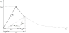
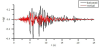
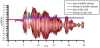
The earthquake record that was relevant to the subway station corresponded to that registered at the Kobe meteorological observatory. The ground motion imposed at the bottom of the model with a depth of 30m is that of Figure 6. As observed from the figure, the maximum acceleration in the horizontal direction was 0.4g and in the vertical direction, 0.15g [28].
3.5 Analysis procedure
Dynamic explicit method [29], based on the central difference method, is used to capture the dynamic and nonlinear behavior of the soil-structure system, which is carried out using the program ABAQUS. Test runs are carried out to determine the length of analysis and time step, and it is found that the above two parameters are adequate in capturing the major response.
Two scenarios are considered in the numerical simulation: horizontal motion only, in the X direction perpendicular to the subway axis (see Figure 5a), is applied at the bottom of the discretization, while the displacement of the Z direction is fixed at the bottom; and the combination of the horizontal motion (X direction in Figure 5a) and the vertical motion (Z direction in Figure 5a). This is done to investigate the effect of the vertical acceleration on the response of the subway station since for design that is often neglected.
4. Results and Discussion
4.1 General response of the Daikai station
The general response of the Daikai station under the scenario of horizontal X motion only is discussed in this subsection.
4.2 Displacement responses
Inertial force is the main factor for surface structures damaged in an earthquake while displacement and strain are more significant for underground structures [30]. Figure 7 shows the time history of relative displacement at the left side wall and middle column.
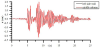
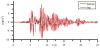
Figure 7 illustrates that the relative displacements at the left side wall and middle column are basically the same, with the peak value 2.15 cm and 2.17 cm respectively, occurred when time is 8.44s. They are both caused by the shearing deformation of the surrounding ground.
4.3 Acceleration responses
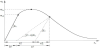
The horizontal motion at the bottom and the top of the station is shown in Figure 8. The peck acceleration of the bottom of the station is 0.61g, which is approximately 1.53 times of the peck input acceleration. And the peck acceleration of the top of the station is 1.03g. It's 2.57 times larger than the peck input acceleration. It is obviously that the acceleration responses of the station are amplified in various degrees, which is also a main factor for the station damaged in the earthquake.
4.4 Stress responses
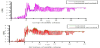
Figure 9-10 show the time history of major principal stress and minor principal stress at 4 representative sites (top of middle column, bottom of middle column, top of side wall, bottom of side wall). It is observed that the stress of the middle column is considerably larger than that of side wall, with the peak value (6.01 MPa) exceeding the concrete tensile yield stress (3.4 MPa).
The middle columns are subjected to large stress causing by shear force, axial force and bending moment. And the results obtained from the research indicate that they are the most severely damage part among the subway structure because of the small cross-section area of the columns and no support constrains around them.
4.5 Damage evolution process
In order to give an insight into the damage evolution process and mechanism of the Daikai station subjected to the earthquake, the expansion of the tensile damage factor dt in the concrete structure is plotted in Figure 11. Note that dt>0 means the concrete begins to damage while dt>1 means the concrete damage completely.

The damage evolution of Dakai station is shown in Figure 11: (a) the concrete of the top and bottom of the middle column begins to damage at time 4.80s; (b) when time is 4.98s, damage extends to the entire cross-section of the middle column immediately so that the top and bottom of the column lose tensile strength and horizontal shear strength; (c) damage occurs at the junction regions between the walls and slabs at time 5.10s; (d) the entire cross-section of the side walls damage completely at time 6.00s and the damage of the middle column extends from the ends to the middle; (e) the top slab damage completely at time 8.40s.
It can be concluded that the collapse of the station attributes to the damage of the middle column. The finding is consistent with the field observations, Figure 1, of central columns of the station completely collapsed and the damage zone located at both ends of the column and the slab.
4.6 The effect of vertical motion
Time history of relative displacement between the top and bottom of middle column under horizontal only and horizontal and vertical seismic motion is shown in Figure 12. Compared with the effect of horizontal motion, vertical motion has little effect on displacement of the station.
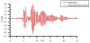
Figure 13 shows the time history of major principal stress of middle column under horizontal only and horizontal and vertical motion. It is obtained that the vertical seismic motion has a minor effect on the seismic response of the subway station. And the dt caused by vertical seismic motion is almost zero all the time. Thus the horizontal seismic motion is the controlling factor affecting the column damage and the vertical seismic motion can generally be neglected.
5. Conclusions
The paper describes in detail the damage observed at the Daikai station, which was adversely affected by the strong Kobe earthquake, and presents a detailed dynamic numerical analysis of the station to reveal the causes and the mechanisms of damage. Evaluation of the damage observed has been done using a refined FEM model of the subway station and surrounding soils that includes non-linear material behavior of the concrete and the equivalent linear model for the soil. Two scenarios are considered in the simulations: seismic input motion in the horizontal transverse direction only, and seismic input motion in the horizontal transverse and vertical directions. This is done separately to investigate the effect of the vertical accelerations on the response of the station. The simulations yield predictions that are consistent with the damage observed at the Daikai station.
The results obtained from the research indicate that the middle columns are the most severely damage part among the subway structure because of the small cross-section area of the columns and no support constrains around them. The vertical seismic motion has a minor effect on the seismic response of the subway station and as a result, it can be neglected for seismic design. The seismic damage mechanism of underground structures is still under investigation. Additional work is currently being taken to analyze more in detail the response of the subway station and also the relative importance of other models for both the concrete and soil. To ensure the functionality of existing underground structures and enable future underground structures to withstand earthquake, further investigation of damages of other structures such as connections between tunnels and subway stations is necessary.
Competing Interests
The authors declare that they have no competing interests.
Acknowledgments
The research has been supported by the National Natural Science Foundation of China (51678438), the Shanghai Rising- Star Program (17QC1400500), and the Shanghai Committee of Science and Technology (16DZ1200302 & 16DZ1201904). The authors acknowledge the support from the State Key Laboratory for GeoMechanics and Deep Underground Engineering, China University of Mining & Technology (SKLGDUEK1723) and the Fundamental Research Funds for the Central Universities of China.