


1. Introduction
Internet technology and new energy technology will promote a new round of energy revolution. The combination of smart grid and "Internet +" technology has become a hot spot in the current electrical engineering field. The concept of energy Internet and Ubiquitous Power Internet of Things (UPIoT) has emerged [1]. The construction of smart grids expands a broader space for development. Among them, the Internet of Things technology is a hot technology in the current scientific and technological field, and its application in the electric power field shows an imaginative prospect. In the deepening construction of smart grids and the rapid development of the ubiquitous power Internet of Things, the 5th generation mobile communication technology has "high bandwidth, high capacity, high reliability, low latency, and low latency" [2]. The characteristics of "power consumption" will become the key technology to lead and support the technological innovation of power system and realize the interconnection of everything. In order to further realize the goal of the smart grid, the power system must make good use of the Internet of Things technology in the 5G era to promote the diversified development of the power system from the traditional power grid to the smart grid, so as to better meet the needs of social development [3].
Due to the explosive growth in the number of power grid equipment, unified identification technology has become the data foundation for the deepening application of the power Internet of Things [4]. At present, smart grids have used QR codes and radio frequency identification (RFID) to uniformly identify equipment, tools and other assets. Radio frequency identification (RFID) technology started in the 1980s, using the spatial electromagnetic field coupling of radio frequency signals to achieve the purpose of non-contact automatic identification and information transmission between tags and readers [5]. However, the traditional backscatter technology has three main limitations: the activation of the backscatter transmitter relies on an external power source, it only responds passively when the reader interrogates, and it is susceptible to the influence of adjacent active readers.
Therefore, environmental backscattering is proposed to assist wireless power communication. In order to solve the problem that the communication distance of the RFID tag is limited by the signal coverage of the reader, the academic community proposed the dualsite backscatter technology in 2013 [6]. In 2014, a turbocharged environment backscatter system with a multi-antenna elimination design and a new encoding mechanism was adopted to improve the communication rate and range [7]. In 2015, the BackFi system proposed by academia significantly improved the WiFi backscattering system, using full-duplex technology to backscatter the WIFI signal in the environment to enable long-distance communication between the sensor and the relay node. In 2016, frequency-shift backscattering transferred the carrier signal to adjacent non-overlapping frequency bands to achieve stronger decoding and achieve 802.1b transmission, which can be more energy-efficient than traditional WIFI, to prove that environmental backscattering is in typical mobile and Practicality in static sensing scenes [8].
In addition, a new fully asymmetric backscatter communication protocol, a new sensor structure of the backscatter platform, and a low-power backscatter system using commercial WiFi are also proposed [9]. At present, the University of Washington has verified the feasibility of this technology through experiments.
The tag antenna is an important part of the environmental backscatter. The tag antenna is a radio frequency signal transceiver that connects the electronic tag and the reader. It radiates the radio frequency signal output by the tag into the space in the form of electromagnetic waves, and at the same time receives and stores the radio frequency signal from the reader [10]. The working frequency of the sub-tag and the electrical parameters of the antenna determine the type of the tag antenna, and are affected by factors such as the radio frequency characteristics of the tag attachment and the metal objects deployed around it. The working frequency bands of microwave electronic tag antennas are concentrated in 800MHz~900MHz, and 2.45GHz and 5.8GHz, using electromagnetic wave propagation coupling [11]. Among them, the signals in the environment used by environmental backscattering are generally 400-600MHz TV signals, 2.4GHz WiFi and 4G and 5G signals, so they belong to microwave tag antennas.
However, there are some problems in the direct application of traditional microwave electronic tag antenna in the power Internet of Things environment.
- The tag communication distance is short. The reading distance of traditional RFID technology is no more than 5 meters. In a typical power Internet of Things scenario, due to the requirements of live working safety distance and the restrictions of some remote and steep terrains, the identification distance requirement for device tags is usually 20-200 meters [12]. Existing technology is difficult to satisfy.
- The label reliability is low. In a strong electromagnetic environment, the label will be damaged and data lost. At the same time, passively induced by the surrounding electromagnetic environment, the tag is frequently falsely activated and shortens its life [13].
- The label energy is unstable. Label access has certain requirements for angle and density. In some scenarios, the dense pasting of the labels causes the distance to be too close, and there is certain interference between each other during reading, which will cause reading failure or excessive time [14]. The label sticking position is obstructed to some extent, which will also cause reading failure.
In order to solve the current problems of traditional tag antennas in the power Internet of Things environment, we design a highperformance tag antenna with miniaturization, directional, high gain, and narrowband characteristics by selecting appropriate substrate materials, antenna structure and optimization.
The rest of this article is organized as follows. The second section introduces the backscatter communication system of the power Internet of Things. The third section describes the structure selection of the antenna and the optimization process of the algorithm. The fourth section presents the simulation and optimization results of the antenna. Finally, the fifth part summarizes the full text.
2. System Model
2.1 Backscatter communication system for power Internet of Things
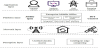
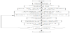
The power Internet of Things uses the power information communication network to realize the efficient transmission, analysis, and processing of smart terminals and equipment information on all links of the power grid, thereby further improving the depth and breadth of smart grid information perception, power system analysis, early warning, self-healing, and disaster prevention [15]. The ability of power grids and the level of safe operation of the power grid can realize the refined management of power from production to consumption, and achieve the goals of energy saving and consumption reduction, as shown in Figure 1. Among them, the unified identification access and intelligent edge computing of the perception layer are the foundation of the power Internet of Things [16].
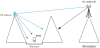
At present, the State Grid Corporation of China has used QR codes and RFID to uniformly identify equipment, tools and other assets, and use backscatter technology to communicate with mobile gateways [17]. However, it has been found to have low reliability and short service life in practical applications. In addition, there are problems of energy consumption and path loss, and the communication distance is greatly shortened. The short communication distance of the tag is also a big problem [18]. The 5G signal has a shorter wavelength and is closer to the straight line of light. In the scene shown in Figure 2, in the power system, some equipment has to be placed in a more precarious environment due to the natural environment, and is more likely to be blocked by obstacles. Traditional tags do not have the function of a radio frequency reflector and cannot bypass obstacles through reflection [19].
The reading distance of traditional RFID technology is no more than 5 meters [20]. However, considering the requirements of the safe distance for live working in the power Internet of Things scene and the restrictions of some steep terrain, the identification distance of the device tag is usually 20-200 meters [21]. To solve this problem, we adopt a passive dual antenna system.
The basic data acquisition equipment belongs to omni-directional transmission and omni-directional reception, but when the tag antenna is arranged in the power Internet of Things system, only the receiving antenna needs to cover as much omni-directionally as possible to collect the signals in the environment, and then use the transmitting antenna to read legally. The position of the device is forwarded. Therefore, the antenna system adopts an omnidirectional receiving and directional transmitting structure.
2.2 Typical tag antenna design scheme
In the design process of the microwave tag antenna, various performance indicators of the antenna, such as antenna bandwidth, pattern, gain, etc., need to be strictly considered, and the material, size, and working distance of the antenna need to be clarified. Common microwave tag antennas include dipole antennas, microstrip antennas, array antennas, and non-frequency variable antennas [22].
2.2.1 Bent dipole antenna
Dipole antenna, also known as element antenna, is a commonly used microwave antenna. In order to make the antenna structure more compact and miniaturized, a curved structure is used. The radiation direction of the antenna radiates omnidirectionally along the plane perpendicular to the bending axis [23].
2.2.2 Microstrip antenna
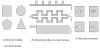
Microstrip antennas are another common microwave antenna. The common one is a planar structure, which is simple and easy to integrate, low cost, and excellent in directivity [24]. It can also be made into a conformal antenna, which is easy to form circular polarization. There are many types of microstrip antennas. According to the structure, they can be divided into microstrip patch antennas and microstrip slot antennas; according to the shape, they can be rectangular, triangular, circular, circular, etc.; according to the working principle, they can be divided into resonant type (standing wave Type) and non-resonant type (traveling wave type) microstrip antenna, as shown in Figure 3 [25].
2.2.3 Array antenna
An array antenna is a form of antenna that arranges multiple radiation sources according to a certain rule or randomly, and obtains the best radiation directivity by adjusting different parameters such as feed current, spacing, and electrical length [26]. Common radiation sources are point source and symmetrical array. With the in-depth research of communication technology, new adaptive array antennas are gradually being promoted to achieve omnidirectional coverage.
2.2.3.1 Microstrip array antenna
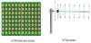
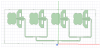
The working frequency of the microstrip array antenna is generally between hundreds of MHz to dozens of GHz, and it is widely used [27]. Its main feature is that both the antenna radiating unit and the feeding network can be made into a microstrip structure and directly connected, making it easy to integrate the transmitting and receiving circuits on a dielectric board. As shown in Figure 4(a).
2.2.3.2 Yagi antenna
The Yagi antenna is an end-fire antenna which is composed of an active vibrator (usually a folded vibrator), a passive reflector and several passive directors arranged in parallel [28]. The Yagi antenna is a typical high-gain directional antenna, which is particularly effective for direction finding and long-distance communication. The antenna installation process needs to ensure that the polarization of the transmitter and receiver is consistent. As shown in Figure 4(b).
Because the traditional electronic tag antenna design is relatively simple and cannot meet the functional requirements of receiving energy and forwarding signals in a specific direction in the environmental backscatter system [29], it is necessary to design a new type of tag antenna to meet the requirements of the power Internet of Things environment. Backscatter system requirements.
3. Antenna Structure Design and Optimization
3.1 Antenna design index
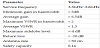
Considering the relationship between the material properties of the dielectric substrate and the bandwidth, size and other properties of the antenna, and considering the radiation loss and surface wave of the antenna, the antenna is selected to be printed on a FR4 board with a thickness of 1.6mm and a relative dielectric constant of 4.4. Feed by the 50Ω microstrip line, the working frequency is 2~4GHz. The design specifications of the antenna are shown in Table 1.
3.2 Antenna design
3.2.1 Receiving antenna structure
Considering that the receiving antenna needs to receive signals from the environment approximately omnidirectionally, the receiving antenna first selects a four-element microstrip antenna. The quaternary microstrip antenna belongs to the standing wave patch antenna. It only has a radiating element on one side of the medium. It can be fed by a microstrip line or a coaxial line, but from the characteristics of the patch antenna, it is not an omnidirectional Antenna, and the bandwidth is relatively narrow. Therefore, the structure of the receiving antenna is improved in this design to make it an omnidirectional broadband antenna.
In the first version of the program design, the most basic rectangular patch was selected for simulation, and the coaxial probe was used to feed power.There are many ways to broaden the frequency band of a microstrip antenna. Because the shape of the patch affects the bandwidth, the patch and floor are often grooved or cut to change the shape of the patch. According to formula (1), the width L of the highefficiency rectangular radiation patch is designed.
In addition, the impedance bandwidth conversion formula can calculate the 50Ω input impedance corresponding to the width of the bottom of the microstrip line = 3mm. By cutting off an isosceles triangle on each of the four corners of the rectangular patch, and cutting off a rectangle on each of the top, left and right sides to achieve a gradual effect. In order to extend the bandwidth, the upper two corners of the grounding plate were cut, and two symmetrical rectangular slots were opened on the grounding plate. In addition, two rectangles are cut under the ground plate to reduce the floor space of the ground plate. The broadband microstrip antenna unit model is shown in Figure 5.

In the antenna design process, by changing the position and size of the cut triangle, the size of the rectangular slot on the ground plate, and the length of the ground plate, the matching of the antenna bandwidth and performance was improved. The improved fourelement patch antenna structure is shown in Figure 6.
3.2.2 Transmitting antenna structure
Because the transmitting antenna is a directional antenna, an endfire antenna such as a log-period dipole antenna is first considered. The log-period dipole antenna (LPDA) is a broadband linearly polarized antenna. In order to make the tag structure more concise, a plane printing structure is adopted to integrate the transceiver antenna on a plane. For the transmitting antenna, the log periodic antenna is a directional end-fire antenna with a wide frequency band. However, in order to cover point-view signals, WIFI, 4G, and 5G signals in the environment as much as possible, the antenna bandwidth needs to be further extended. Therefore, the log-period antenna still has room for improvement.
From the antenna analysis theory, it is known that attaching parasitic patches near the logarithmic period long array is similar to the design of expanding the bandwidth of the Yagi antenna, which can effectively change the resonance mode, thereby broadening the bandwidth of the antenna. The antenna structure is shown in Figure 7. The length of the antenna element is denoted by Ln, and the extension of the end of each antenna element intersects at a point, called a virtual vertex, and the opening angle is α. Denote the vertical distance from the virtual vertex to each antenna element as Rn, the width of the element as Wn, and the distance between two adjacent elements as dn.
The geometric structure of the antenna is determined by the geometric factor τ and the spacing factor σ.
The number of antenna elements can be obtained by the following formula:
Among them, K1 and K2 are cutoff coefficients.
In addition, it is also necessary to estimate the width of the vibrator.
LPDA is a directional end-fire antenna, and the maximum radiation direction is from towards the short dipole end. Generally speaking, the larger the value, the greater the number of oscillators in the radiation area, the stronger the directivity of the antenna, and the smaller the half-power angle of the pattern. The length of the longest vibrator and the shortest vibrator of LPDA determines its operating frequency.
LPDA is a linearly polarized antenna. When the vibrator of the LPDA is placed horizontally, it will radiate or receive horizontally polarized waves; when placed vertically, it will radiate or receive vertically polarized waves. Therefore, it is easier to achieve circular polarization with a planar structure.
3.2.3 Antenna structure determination
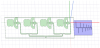
The final antenna structure consists of a broadband microstrip antenna array and a log-period dipole antenna, as shown in Figure 8. Both antennas are broadband antennas, and the frequency meets the 5G signal requirements. The microstrip antenna array is responsible for receiving signals in the environment and forwarding them through a log-periodic antenna. There are fewer side lobes. Since the feed end of the log periodic antenna is at the short end, it cannot be directly connected. It is necessary to connect the feed network of the microstrip array to the feed end of the log periodic antenna through a coaxial line.
3.3 Antenna optimization
3.3.1 Multi-objective genetic algorithm
Genetic algorithm is a global algorithm that simulates natural selection and survival of the fittest, and evolves generation by generation to find the optimal solution [30]. The algorithm starts from the initial population of the first generation and evolves from generation to generation to get closer to the optimal solution [31]. In each generation, the fitness function is calculated according to the solved target, sorted and selected according to the fitness from high to low, and one or more points of crossover mutation are performed with the help of genetic operators to generate the progeny population. When the fitness meets the requirements or the number of cycles reaches the set number of iterations, the outstanding individuals of the last generation are the results of the final search [32]. Genetic algorithm has the advantages of not relying on gradient information and strong robustness, so it is widely used in the field of electromagnetic engineering, especially antenna design.
The traditional solution to multi-objective problems is to convert multi-objectives into single objects, such as weighting or constraints, and searching with single-objective solutions. However, the shortcomings are also obvious. The weights of multiple targets need to be set by themselves, and only one solution can be generated per calculation [33]. The MOGA used in this paper can obtain the Pareto solution set of multiple objectives at once.
This paper adopts NSGA-Ⅱ genetic algorithm and introduces the concept of Elitism. On the basis of traditional genetic algorithm, a non-dominant sorting process is added, that is, the parent and offspring are mixed and then sorted and selected to prevent the loss of outstanding individuals from the parent. At the same time, in order to maintain the diversity of the population, density estimation and comparison operators are used in the selection of the binary tournament to effectively prevent local convergence. Therefore, this article makesthe above selection, and the algorithm flow chart is shown in Figure 9.
3.3.2 Application of multi-objective genetic algorithm
Since the directional antenna has a greater impact on the physical layer security, and the structure of the log-period dipole antenna is more complicated, the transmitting antenna is used as the optimized antenna. Select the length, width and spacing of the vibrator as the variables to be optimized. In the antenna design process, the gain, bandwidth, and sidelobes of the antenna are important indicators to measure the performance of the antenna, so the functions corresponding to the above three indicators are defined as the objective function.
A multi-objective optimization problem with 3 decision variables and 3 objective functions can be expressed as
Among them, represents the objective function vector, represents the objective function, Define X and Z to represent the search space and target space respectively, and use the mapping to indicate that each vector corresponds to the vector
Limit the length of the high-order vibrator to be greater than the length of the low-order vibrator, and take values within a suitable range. According to the physical meaning of the variable, the optimization range L∈[30,200], d∈[0.5,20], w∈[2,7] (unit: mm) is given.
3.3.2.1 Bandwidth
The target frequency band ranges from 2 GHz to 4 GHz and is determined by a 10 dB return loss. In order to achieve this goal, the fitness function is defined as the end value of the return loss S11 that does not exceed -10dB in the frequency band of interest minus the start value.
Where fstop and fstart are the stop frequency and start frequency that satisfy S11<-10dB, which is:
In the above equation, fi is the sampling frequency. If the average value of S11 at the sampling frequency is less than -10 dB, we believe that the design goal has been achieved. In the design example, the sampling frequency is N= 21. When P(x)≥10, the objective function is satisfied.
3.3.2.2 Gain
The antenna gain measures the ability of the antenna to send and receive signals in a specific direction, so it is also used as the optimization target of this design. Take the average gain in the frequency band as the objective function:
3.3.2.3 Sidelobes
Because the antenna pattern will produce many side lobes, and the level of the maximum side lobe is often similar to the maximum gain of the antenna. In the physical layer security, there are strict requirements on the directionality of the antenna, and the peak value of the highest side lobe needs to be reduced as much as possible. Therefore, the optimization goal is to minimize the first sidelobe level.
According to the designed optimization plan, 35 variables including the length of the vibrator L1~L12, the width of the vibrator w1~w12 and the distance between the vibrators d1~d11 are selected as the optimization variables.
Crossover is the process of generating new individuals, which can perform a global search in the solution space to prevent premature convergence [34]. Mutation is to ensure the diversity of the population [35]. In this article, we choose two-point crossover, that is, to extract a pair of individuals at a time according to the crossover probability, randomly select two points as the crossover point, and then exchange the code segments between the two points to generate two new individuals.This article uses binary coding, so the selected mutation method is the basic bit mutation, which is to extract an individual according to the mutation probability, and then randomly select one bit from the individual to perform the inversion operation.
We set the population size to 10, the maximum number of iterations to 50, the crossover probability to pc= 0.7, and the mutation probability to where is the number of decision variables. The frequency is sampled at 100MHz intervals in the 2GHz~4GHz band. All the dimensions of each individual are transferred to the electromagnetic simulation software HFSS, the objective function is calculated, and then passed back to the genetic algorithm for selection, crossover, mutation and calculation of the next generation population, and iteratively. When the fitness function meets the set requirement or the number of iterations reaches the limit, the algorithm ends and the optimized antenna size is obtained. Fuzzy set theory provides a method to derive the best compromise solution from the Pareto front. According to the modeling of the linear fuzzy membership function, the objective function value is mapped to the satisfaction function.
4. Simulation Results
4.1 Simulation analysis of receiving antenna
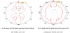
The pattern of the improved quaternary patch antenna is shown in Figure 9. It can be seen that the E side is an omnidirectional antenna, and the H side is affected by the arrangement of the patch array, but it can be directed toward the upper and lower half spaces at the same time. radiation. The gain of the quad antenna array is 7.85dB at 2.4GHz. The feed network will increase some loss, but the impact on the antenna performance can be ignored, as shown in Figure 10(a) and 10(b).
4.2 Simulation analysis of transmitting antenna
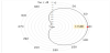
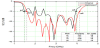
The improved log-periodic antenna pattern and bandwidth are shown in Figure 11, Figure 12, and Figure 13. It can be seen from the figure that the improved log-period antenna bandwidth is 1.76GHz~3.96GHz, that is, the bandwidth of 2.2GHz. Compared with the 300MHz bandwidth extension before the improvement, the gain is about 5.71dB, and the directivity is basically unchanged.
The optimization result of log-period dipole antenna using multiobjective genetic algorithm is shown in the figure below.
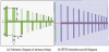
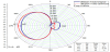
In Figure 14, a comparison of the directional patterns before and after optimization is shown. The antenna gain is optimized from 5.71dB to 7dB. Before optimization, there is a large side lobe, and the maximum side lobe level is -4dB. After optimization, the maximum side lobe is reduced to -5.76 dB, which effectively enhances the directivity of the antenna.
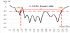
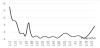
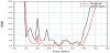
The curves shown in Figure 15 and Figure 16 respectively show the change of return loss S11 and VSWR with respect to the frequency before and after optimization. It can be seen that the optimized 10dB impedance bandwidth is 2.5GHz, and the average VSWR in the frequency band is 1.3, reaching the expected goal.
5. Conclusion
The environmental backscatter technology is gradually popularized and used because it gets rid of the energy coverage limitation of the reader in the Internet of things communication. Based on the ubiquitous power Internet of Things and 5G technology, this article discusses the important role of backscatter communication technology in the smart grid, and aims at the short communication distance, unstable energy and low reliability of existing tag antennas. From the perspective of the physical layer, design a tag antenna with a dual-antenna structure, while taking into account the functions of its own energy supply and signal forwarding. And use multi-objective genetic algorithm to optimize the antenna size. Later simulation results show that the antenna gain is obvious, the sidelobe is small, the bandwidth is as expected, and the anti-interference is strong. It solves the low reliability and unstable energy extraction of traditional microwave electronic tag antennas used in the power Internet of Things environment. It meets the information transmission requirements in the power Internet of Things scenario.
Competing Interests
The authors declare that they have no competing interests.