


1. Introduction
Future wireless communication systems require broader frequency bands to realize larger capacity because of the rapid spread of smartphone and the development of IoT (Internet of Things). Spectrum sharing is one of the promising technologies to yield broader bands with limited frequency resources, in which plural systems share the same frequency bands, and the secondary system uses unused bands in the allocated bands to the primary existing system [1-4]. Because the unused bands are narrow and separated, the secondary system needs to simultaneously use multiple bands to transmit broadband information signals.
On the other hand, OFDM transmission, which is very effective in broadband transmission in multi-path fading channels, is widely used in wireless communication systems while it causes excessive peak power which generates in-band and out-of-band noise because of non-linear distortion of transmission power amplifiers. In addition, multi-band transmission with OFDM causes serious distortion noise by inter-modulation distortion. The distortion noise of a multiband system becomes harmful interference to the existing system in spectrum sharing. Therefore, effective power amplification for multiband transmission has been studied [5-7].
This paper proposes a non-linear distortion noise power control method with bandwidth control for multi-band OFDM transmission systems to reduce interference to the spectrum shared existing system in wireless communications. The control method generates out-ofband noise reduction signals using a part of used signal bands to reduce interference. The method uses clipping and filtering (CAF) for this noise control, which is one of the very effective peak power reduction methods of OFDM signals [8-10]. The conventional CAF usually uses out-of-band filtering which reduces out-of-band noise power caused by clipping. In addition to this filtering, the proposed method uses in-band filtering which removes in-band distortion noise components from clipped OFDM signals. This paper clarifies the effect of distortion noise power control with the proposed method by computer simulations.
2. Multi-band Transmission Systems
2.1 System Model
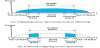
Figure 1 shows the system model in this paper. A secondary multi- band system shares the same frequency bands with a primary existing one. The service area of the secondary system overlaps with that of the primary one. Therefore, the transmission signals of the secondary multi-band system become interference to base and mobile stations of the primary one.
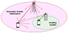
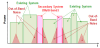
Figure 2 shows frequency usage of spectrum sharing systems in this paper. The frequency bands are allocated to the primary system, and the unused bands among them are used by the secondary one. The secondary system simultaneously uses multiple frequency bands as shown in Figure 2. This use can realize highly efficient frequency utilization and broadband transmission with limited frequency resources. However, when multi-bands are used simultaneously, serious in-band and out-of-band distortion noise occurs by nonlinearity of a transmitter. The distortion noise increases by using OFDM transmission employed in current wireless communication systems because the peak power of OFDM signals is larger than that of single carrier transmission. This distortion noise interferes transmission signals on the bands used by the primary system when the service areas of two systems are overlapped. To realize spectrum sharing, the secondary multi-band system needs to reduce the interference so as to satisfy transmission quality for the primary one.
2.2 Transmitter with bandwidth control
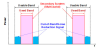
Figure 3 shows the transmitter for multi-band OFDM transmission with bandwidth control. Transmission signals are mapped to modulation symbols and allocated to multiple frequency bands. The bandwidth of each band is controlled to reduce in-band and out-ofband distortion noise which is harmful interference of the primary system. Figure 4 shows the method of bandwidth control for the secondary system. The method controls the bandwidth used by the secondary system so as that each used band becomes narrower than the usable one. This control can generate unused bands in the usable bands as shown in Figure 4.
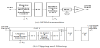
The signals with bandwidth control are transformed into OFDM signals by IFFT in Figure 3(a). The peak power of the OFDM signals is larger than saturation power of the used power amplifier, and it results in much distortion noise out of transmission signal bands. Then, before power amplification, clipping and filtering, CAF, are performed to reduce such peak power of OFDM signals.
2.3 Clipping and filtering
The CAF part is shown in Figure 3(b). At the clipping and peak power detector, peak signal components exceeding the set clipping level in OFDM signals are detected in the time domain as shown in Figure 5. These detected peak signals are equivalent to removed components by usual clipping. The detected components are transformed into inband and out-of-band clipping noise of the frequency domain by FFT.
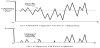
Figure 6 shows filtering for clipped OFDM signals in this paper. The filtering part in Figure 3(b) removes the clipping noise. Two methods can be used as this filtering. One is out-of-band filtering which removes clipping noise generated outside usable bands by intermodulation distortion as shown in Figure 6(a). The other is in-band filtering which removes clipping noise added on the used signal bands [11]. The in-band and out-of-band filtering leaves clipping noise in only unused bands as shown in Figure 6(b). The remained clipping noise becomes out-of-band noise reduction signals.
The filtered signals are transformed into peak power components of OFDM signals in the time domain by IFFT in Figure 3(b). These transformed signals are subtracted from the original OFDM signals.
Although the peak power of OFDM signals are reduced by this CAF, the peak reduction becomes imperfect because in-band and out-of-band filtering removes a part of clipping noise. To reduce peak power to the set clipping level, the CAF is repeated. These peak power reduced OFDM signals by iterative CAF are modulated by a quadrature modulator and amplified by a non-linear power amplifier.
2.4 Frequency band usage
Figure 7 illustrates used band allocation methods in one usable band for the multi-band system. There are 4 types in the methods. These differ on the allocation of unused bands in which out-of-band noise reduction signals are generated by iterative CAF.
Type 1 sets unused bands outside the usable band, and the number of its used band is 1. Type 2 sets one unused band inside the usable band, and its used bands are divided into 2. In Type 3, the usable band is first divided into 2, and the same allocation as Type 1 is performed. This results in 2 used bands and 3 unused bands. Type 4 also divides the usable band into 2 bands, and the same allocation as Type 2 is employed. Type 4 has 3 used bands and 2 unused bands. In the following, the distortion noise reduction effects with these allocation types are evaluated.
3. Simulation Results
3.1 Simulation condition
Computer simulations were conducted to clarify the effect of the proposed method in multi-band transmission with OFDM. Spectrum properties and SNR improvement with the proposed method were evaluated in a receiver of the primary existing system.
Table 1 shows simulation conditions in this paper. The modulation scheme was 64QAM, and the total FFT point number was 16384. The number of transmission frequency bands, Nb, was set to 1 and 2 for the primary existing and secondary multi-band systems, respectively. The sub-carrier number for single band was 600, and it was 1200 for the multi-band system.
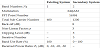
The input back-off values of non-linear amplifiers (NLAs) were set to be 8 dB for both systems. In this paper, the typical model of an NLA was used [12]. The non-linear factor of the model was set to be 3. The clipping level was 3 dB, and iteration number was 5 in iterative CAF for bandwidth control in the multi-band system.
The ratio of used bandwidth to usable one was set to be 0 to 100 % for the multi-band system by bandwidth control, and it was 100 % for the primary existing system.
The received power ratios of the existing system were set to be 0 dB, -10 dB, -20 dB, and -30 dB to the spectrum sharing multi-band system.
3.2 Spectrum properties by spectrum sharing
Figure 8 shows received spectrum properties of a secondary multiband system with and without CAF at an existing system receiver. The band utilization method of Type 1 was used in this figure. The frequency of horizontal axis is normalized by the sampling rate 1/T of OFDM symbols. The band use rate by bandwidth control with CAF was set to be 60 %. The received spectrum of the existing system is also shown in Figure 8, and the power ratios Pr are set to be 0 dB and -30 dB in Figure 8(a) and (b), respectively. The existing system uses the band of third inter-modulation distortion caused by the multi-band system.
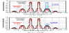
Figure 8(a) shows that bandwidth control by using CAF is effective in the reduction of out-of-band noise by third inter-modulation distortion. The figure also shows that the occupied bandwidth of outof- band noise on third inter-modulation band becomes narrower, and the bandwidth becomes 60 % which is equal to the set band use rate.
In addition, Figure 8(b) shows that the bandwidth control is more effective in Signal-to-Noise Ratio (SNR) improvement at lower power ratios of the existing system because interference power from the multi-band system is decreased by out-of-band noise power reduction.
Figure 9 also shows received spectrum properties with and without CAF. The band utilization method of Type 1 was used. The band use rate by bandwidth control was set to be 60 %. The power ratios Pr are set to be 0 dB and -30 dB in Figure 9(a) and (b), respectively. In these figures, the existing system uses an adjacent band of the multi-band system.
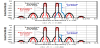
Figure 9 (a) shows that bandwidth control by CAF can significantly reduce out-of-band noise on the adjacent band of the multiband system, and the noise power reduction of 12 dB is obtained. Furthermore, Figure 9(b) confirms that the bandwidth control can improve SNR performance of the existing system at lower power ratios.
3.3 SNR improvement by bandwidth control
Figure 10 shows SNR improvement of the primary existing system when the secondary multi-band system employs bandwidth control by iterative CAF. In this SNR improvement evaluation, the total noise power N of SNRs is calculated by the following equation.
where Dp is own distortion noise power of the existing system caused by its transmitter non-linearity, and Ds is the distortion noise power received from the multi-band system. The existing system uses the band of third inter-modulation distortion by the multi-band system. The band utilization methods of Types 1 to 4 were used in this figure.
The band use rate of a multi-band system is set to be 0 to 100 %. The value of 100 % is without bandwidth control, and 0 % means that the multi-band system uses no frequency band. SNR improvement is represented by the difference for the SNR at 100 %.
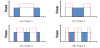
Figure 10 (a) shows SNR improvement evaluation results at the power ratio Pr of 0 dB. This figure shows that the effect of bandwidth control is very small at all band use rates. These results are because the received signal power is sufficiently large, and own distortion noise power Dp is larger than Ds from the multi-band system. This results in small influence of distortion noise power reduction by bandwidth control. There is no difference by allocation types in usable bands of the multi-band system.
Figure 10 (b) shows SNR improvement at Pr of -10 dB. This figure shows that bandwidth control is effective in SNR improvement. It can improve by 2 to 3 dB at the band use rate of less than 60 %. The difference by allocation types is not much. Because the received signal power and own distortion power Dp is still large, the reduction difference of distortion power Ds by allocation types does not appear to the evaluation results.
Figure 10 (c) shows the evaluation results at Pr of -20 dB. This figure shows that the improvement of bandwidth control is larger than that of high power ratios. The improvement values reach to 5 dB at a maximum. The figure also shows that the selection of allocation types is effective. Types 3 and 4 can be more reduced by about 2 dB compared with Types 1 and 2. Because types 3 and 4 divide the bands of out-of-band noise reduction signals, they can reduce distortion noise of more frequency. In addition, because used signal bands are divided, noise by third inter-modulation distortion spreads and its power per sub-carrier becomes lower. This results in distortion noise reduction within the band used by the existing system, and the SNR is improved.
Figure 10 (d) shows evaluation results at Pr of -30 dB. This figure shows that the improvement of bandwidth control is the same as that at -20 dB. The maximum improvement value is 5 dB at the band use rate of 10 to 60 %. At less than -20 dB, distortion noise from the multiband system, Ds, is dominant in the used signal band of the existing system. Therefore, the improvement values of SNRs are equal in spite of power ratio lowering.
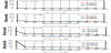
(Third inter-modulation distortion band).
Figure 11 shows SNR improvement evaluation results by the bandwidth control. In this evaluation, the existing system uses the adjacent band of the multi-band system as shown in Figure 9. Allocation types of Types 1 to 4 were used in the evaluation. The band use rate of the multi-band system is set to be 0 to 100 %.
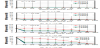
(Adjacent band).
Figure 11 (a) shows the evaluation results at the power ratio Pr of 0 dB. This figure shows that bandwidth control has almost no effect on SNR improvement of the existing system. The reason is the same as the case of third inter-modulation distortion band, and it is because the received signal power is sufficiently large, and Dp is larger than Ds. The results also show that there is no difference of SNR improvement by allocation types.
Figure 11 (b) shows evaluation results at Pr of -10 dB. This figure shows that bandwidth control is effective in SNR improvement of the existing system at -10 dB. It can improve by 4 dB at the band use rate of less than 50 % by using Type 1. The reduction values are almost the same as that of 100 % in which the multi-band system uses no frequency band. Because the unused band for out-of-band noise reduction signals is close to the adjacent band used by the existing system in Type 1, the leakage distortion power from the multi-band system can effectively be reduced. On the other hand, the used signal band of Type 2 is close to the adjacent band. Therefore, the distortion noise power reduction effect of Type 2 is smaller than that of Type 1.
Figure 11 (c) shows the results at Pr of -20 dB. This figure shows that the improvement of bandwidth control is larger than that of high power ratios. The improvement value reaches to 10 dB at 50 % at a maximum. The figure also shows that the difference by allocation types is very significant in case of the adjacent band. Type 1 can especially obtain larger SNR improvement compared with other allocation types. At this power ratio region, Ds is dominant in SNRs, and larger Ds reduction effect by bandwidth control of Type 1 remarkably appears in SNR improvement.
Figure 11 (d) shows the results at Pr of -30 dB. This figure shows that the improvement of bandwidth control is larger than that of -20 dB. The improvement value with Type 1 becomes 15 dB at 50 %. The value becomes 6.5 dB even at 80 %. In addition, Type 3 can improve the SNR of the existing system by 6 dB at less than 60 %.
The above results confirm that the SNR improvement of the adjacent band is larger than that of third inter-modulation distortion band. This is because the band allocated to out-of-band noise reduction signals becomes near distortion noise to be reduced.
Although Types 3 and 4 are more effective in distortion noise reduction in third inter-modulation distortion noise band from the results of Figure 10, the difference of reduction effect is not large. On the other hand, the advantage of Type 1 is obvious in the adjacent band from the results of Figure 11. These result shows that Type 1, which allocates unused bands outside usable bands, is superior to other allocation types on distortion noise reduction.
4. Conclusion
This paper has proposed a non-linear distortion noise power control method with bandwidth control for multi-band OFDM transmission by spectrum sharing, which uses iterative clipping and filtering. The method employs in-band and out-of-band filtering to effectively control non-linear distortion noise power and improve SNR performance. The evaluation results with the proposed method show that it can reduce out-of-band distortion noise power of a secondary multi-band system and improve the SNR performance of a primary existing system. The results confirm that spectrum sharing is feasible even in multi-band systems.
Competing Interests
The authors declare that they have no competing interests.