


1. Introduction
The processes of requirements analysis, definition and management are essential to address the design and implementation of any application. Meeting the functional requirements of a product is directly related to its effectiveness. In general, an effective system is one that provides the functionality to fulfill its requirements. However, the concurrence of additional, non-functional requirements might prevent the implementation of all the expected functionality. Usually, there are several combinations of algorithms that solve a particular problem with the same effectiveness. Then, the choice of one or other depends on the degree in which they improve other requirements such as efficiency. A vision system is more efficient if features such as speed, accuracy, etc. are incremented and the amount of consumed resources such as memory, processing, energy, etc. are decremented.
In order to increase the efficiency of the tasks related to image processing, we could use two approaches: (1) to improve the efficiency of algorithms (software approach) or (2) to run these algorithms on a more powerful platform (hardware approach). Because vision systems are by nature heterogeneous systems, it is possible to combine the expressiveness and flexibility of programming languages with the efficiency of hardware. Therefore, we can create more flexible solutions to delay the choice of hardware and improve current designs by using different development paradigms offered by Software Engineering.
Traditionally the majority of research within the software for computer vision field focuses on creating new algorithms and methods for performing the analysis and manipulation of the image data. The lack of focus on system development issues has forced system developers to explicitly deal with low-level data management details. As some authors have indicated for robots programming [1], some of the underlying causes include: variability in the type of applications and components that are used in that domain; difficulty of reuse owing to the blurring of frontiers between architectural elements of different types (device managers, algorithms, middleware, etc.), and lastly the lack of interoperability between tools used in the different development stages.
In this context, Component-Based Software Development (CBSD) is a design alternative that favors the reuse of software elements and facilitates the development of systems from pre-existing elements. A software component is a unit of composition with well-defined interfaces and an explicit use context. As established in [2], the principles of CBSD can be applied in practice either by considering the components as objects or by considering them as architectural units [3]. CORBA Component Model [4] is an example of the first case, while Architecture Description Languages (ADLs) [5] are examples of the second case. The benefits of adopting the first approach (components as objects) derive from the broad dissemination of this technology (tools, implementation environments, etc.). However, object orientation (OO) defines interaction mechanisms (method invocation) that tend to couple the objects and hinder their reuse. On the other hand, considering the components as architectural units obviates the above drawbacks, since they only interact through their ports, thus reducing coupling and facilitating reuse.
The development of applications based on a CBSD approach, where the components are considered as architectural units, still requires solutions to two problems: (1) to have a set of techniques, tools and methods to support that approach, and (2) to define and implement a series of mechanisms to convert the CBSD designs to executable programs (i.e. a compiler for a component-based language). Model Driven Software Development (MDSD) approach [6] provides the theoretical bases and the tools necessary to solve the above two problems.
Following the MDSD approach, a system can be represented at a certain level of abstraction using models. With the right selection of levels of abstraction it is possible to separate software artifacts that are independent of the implementation platform and ones that are not. Models are therefore the main artifacts driving the development process. According to [7], these models are simplified representations of reality in which non-relevant details are abstracted, thus improving both comprehension and communication of the reality underlying these models. The models are defined as meta-models, which embody the concepts relevant to a particular domain of application, and also the relationships between them (in other words, they represent the abstract syntax of the language). Model-to-model transformations [8] are also key mechanisms in MDSD, defining as they do the way in which these models will be interpreted and transferred to other representations at the same or a different level of abstraction, until finally code is generated in an implementation language. In summarize, the first problem can be solved, at least in part, by defining metamodels with which to build models of applications using the CBSD approach. Model-to-model transformations provide a mechanism with which to solve the second problem. Although relatively novel, MDSD has produced promising results in applicable domains such as automotive, aviation and electronics among others [9].
In order to maintain a generic software approach, the solution adopted to transform component models into executable code should be validated for a set of computer vision applications that share certain minimum features. In terms of implementation, software frameworks are the artifacts that offer the highest level of code reuse and flexibility, given that it is possible to consider semi-complete applications which are specialized to produce concrete applications [10]. A framework embodies the features common to many applications in the domain of interest, and at the same time offers specialization mechanisms and points of variability with which to specify differences. In this way, the Software Product Line (SPL) paradigm is considered for obtaining its obvious advantages [11]. Frameworks are designed using design patterns and integrate the architectural decisions using the same artifacts to model and build all the products of a family ViSel-TR enhances the flexibility and reuse of designs using the previous paradigms offered by Software Engineering. To show the novel approach and validate it, this article shows the development of a selective vision for cataloguing road signals in order to facilitate the performing of maintenance operations. This application has been developed incrementally un four scenaries, with the help of C-Forge [12], which is an Eclipse-based Model-Driven tool-chain for supporting a component-based development process that relies on: (1) a component model (WCOMM) for modeling applications by means of components, ports and connections among them and, (2) a component framework (FRACC) that provides the runtime support for executing the component-based application modeled with WCOMM.
The ViSelTR main feature that has allowed to ensure compliance of all requirements in unstructural environments, it has been the capacity to reduce the amount of visual information that the computer vision system has to process. For that, -ViSelTR has used a set of sensors which supply non-dependent data of the visual information captured by the cameras, such as illumination, global robot position (GPS), meteorological information, speed, time, etc. With this new approach, the vision system will be capable of processing visual information in real-time because the selected scenario is previously known.
In the following section, this article describes related works that include the use of the above-mentioned paradigms to develop computer vision applications. Section 3 describes the architectural guidelines that have been considered as a starting point for obtaining a generic software architecture for vision systems that will operate in unstructured environments, and describes the architecture that will be translated to components. Section 4 briefly describes C-Forge as well as the case study used to validate the proposed approach. Finally, sections 5 and 6 present conclusions and future works.
2. Related Works
Despite the expected benefits of using the CBSD approach in software development, there is no complete evidence of its application on a large scale. Among general-purpose component models, we may cite Fractal [13], the CORBA component model [4], KobrA [14], SOFA 2.0 [15], SaveCCM [16], and Koala [17], among others. Fractal provides an ADL to describe the architecture of the applications and a framework for implementation of the components in Java and C/ C++. SOFA provides a similar approach, which enables component distribution and updating, although limited to the Java language. The CORBA CCM model was developed to build componentbased applications on the CORBA communication middleware and provides an IDL (Interface Definition Language) to generate the external structure of the components and facilitate their integration in the middleware. Koala is the first component model applied to the electronics sector; it was developed by Phillips and used as a base to develop the software for their consumer products. KobrA is one of the most popular proposals, in which a set of principles is defined to describe and decompose a software system following a downstream approach based on architectural components. But in all cases the implementation of the code and structure of the component is still completely dependent on the developer.
For a slightly different approach to the foregoing, we may consider Cadena/CALM [18], which is an Eclipse environment for the design of component-based Software Product Lines (SPL). With Cadena, the designers first select the target component model and then the environment provides the definition of the SPL on that basis. In our view, selection of the target platform so early on is a drawback to the approach, as it forces the user to adopt a component technology from the outset. In our proposal, selection of the platform is postponed until as late as possible.
Most of these models only deal with the structural modeling of the application, leaving implementation of the logic of the components (and hence their behavior) to the manual codification stage. Save CCM is an exception in that it includes the modeling of behavior, albeit with constraints deriving from the characteristics of the domain in realtime systems. In this field, there have been very promising results with the MDSD approach. Significant examples include the ArtistDesign Network of Excellence in Embedded System Design [19] and the OpenEmbeDD project [20]. Then also, in the automotive field the industry has standardized AUTOSAR [21] for vehicle development following this approach.
In relation to frameworks new, more general and innovative proposals have recently appeared in the literature, focusing on the development and use of frameworks for software systems development in general [22,23]. In [22], the authors propose a method for specialization of OO frameworks using design patterns, which provides a design fragment for the system as a whole. A design fragment, then, is a proven solution to the way the program should interact with the framework in order to perform a function. The idea is for each framework to have its own catalogue of design fragments, offering conventional solutions to known problems. The proposal is validated with an Eclipse-based tool containing more than fifty patterns.
Antkiewicz and Stephan [23] go a step further by providing a conceptual and methodological framework for the definition and use of framework-specific modeling languages (FSML). An FSML is an explicit representation of the specific features of a domain as offered by the associated framework. For instance, FSML can be used to express “framework-specific” application models. These models describe the instances of the features supplied by the framework that are ultimately implemented in the application’s code. The last two works cited very clearly illustrate the trend in the development of framework-based applications for the coming years and should therefore be borne in mind in any proposal in that connection.
In the context of vision systems, some our experiences can be found in [24,25] or [26].For example, [27] describes a generic architecture for the development of these systems from the study of three prototypes used for the industrial sector structured environments. To obtain the architecture, the methodology COMET [28] is applied. In the architecture described in [27], three subsystems are identified: (1) product inspection, (2) configuration and calibration of system parameters, and (3) alarm management. In all cases, we observe the same pattern for the inspection work: (1) the captured images are processed to identify objects, (2) each object is characterized by a series of visual properties, and (3) a classifier determines product quality based on these properties. As a continuation of previous work, as part of the core of common resources, two additional elements are incorporated: (1) a library of software components for image processing that integrates the functionality offered by several existing libraries, and (2) a visual programming tool called IP-Code to automatically generate prototypes. This tool is limited to the development of vision systems that work in a structured environment, and lacks a system to facilitate the selection of algorithms.
Other works describe some libraries that attempt to address the subtasks of vision system development, such as OpenCV [29], VXL [30] and Gandalf [31]. The approach offered by these frameworks is to expose image access, manipulation and processing routines through a function based API. However, there are a number of significant shortcomings that are inherent to the design and approach utilized by these libraries. Firstly, they do not provide a clear definition of vision components. The functionality for accessing, manipulating and processing routines is offered to the users at the same abstraction level, using the same API. Users are forced to deal with low-level operations such as pixel manipulation and high-level operations such as searching for features in the whole image. Secondly, these frameworks do not provide a comprehensive solution for vision system development, although OpenCV provides a camera access mechanism, the solution offered is intermediate and incomplete, also there is no support for transportation of vision data in these frameworks. Thirdly, the API offered by these frameworks provides poor support for modularization. These frameworks essentially provide a set of functions and do not address the need for developing code that is easily reused or can be scaled to larger systems.
Open CV is probably the most widely used vision library for extraction and processing of meaningful data from images. However, because OpenCV assumes essentially a sequential software architecture, the potential acceleration resources in computer vision are fully explored to improve performance. Moreover, the OpenCV library does not support multi-camera streams, which limits the system scalability. Khoros [32], an integrated software development environment with a collection of tools for image and digital signal processing, uses pipes and filters as their underlying architecture model [33]. This pattern supports parallel and distributed processing, is more appropriate for a system processing a stream of data.
Open VL (Open Source Vision Library) is designed to address efficiency, reusability and scalability [34]. Inspired by the success of OpenGL, the intent of OpenVL is to allow users to quickly and easily recover useful information from multiple real scenes (multi-camera systems), and in a portable manner across hardware platforms. By providing a hardware development middleware that supports different hardware architectures for acceleration, OpenVL allows code reuse without compromising performance. Finally, as an evolution of OpenVL, [35] presents the Vision Utility (VU) framework, which decomposes the task of vision system development into data processing and management. VU refers to the task of processing images which includes both analysis and manipulation of image data as data processing, and to the tasks of (1) decoupling access to source data from processing, (2) hiding image data format details from users and (3) provide abstraction over inter-component communication as data management.
3. Software Architecture for Vision Systems: From Structured to Unstructured Environments
Visual information processing in unstructured environments requires taking into account the functional requirements and the architectural guidelines followed for developing vision systems that work in structured environments, while incorporating additional requirements and design aspects. Thus, in this section, some architectural guidelines are summarized in relation to: (1) nonfunctional requirements, (2) design patterns and (3) hardware processing issues. A functional description of vision system’s components is also shown.
In relation to non-functional requirements in computer vision applications, there are three main systems implementation issues [34]:
- Efficiency: Many computer vision applications, such as nearly all surveillance systems, require real-time performance, which means that the systems must interact with their environments under response-time constraints. Improving efficiency of the algorithms helps to meet these constraints.
- Reusability: Dedicated and heterogeneous computer vision processing platform have made it difficult for software developers to port their applications from one hardware platform to another.
- Scalability: Significant decreases in camera prices have made multi-camera systems possible in practical applications. It is necessary to provide mechanisms to maintain correspondence among separate but related video streams at the architectural level.
In relation to design patterns, as mentioned above, compared to sequential software architecture, a pipes and filters architecture [33], which naturally supports parallel and distributed processing, is more appropriate for a system processing a stream of data. This pattern is used traditionally for vision systems development. In the pipes and filters architecture, each component has a set of inputs and outputs. The components, termed filters, read streams of data as inputs and produce streams of data as outputs. The connectors, called pipes, serve as conduits for the streams, transmitting the output of one filter to the inputs of another.
The pipes and filters architecture has a number of features that make it attractive for these applications: (1) this architecture allows the designer to understand the overall input/output behavior of a system as a simple composition of the behavior of individual filters, (2) this architecture supports reuse: any two filters can be connected together, provided they agree on the data format being transmitted, (3) the pipes and filters architecture provides an easy synchronization mechanism, because filters do not share data with other filters and (4) because data-processing objects, i.e., filters, are independent, this architecture naturally supports parallel and distributed processing. However, the general pipes and filters architecture has its own disadvantages (for example, because filters do not share state information with other filters, the architecture does not provide any mechanism for users to reconfigure the data flow routine in run time).
Finally, since three decades ago, the use of hardware platforms with parallel processing is necessary to support real-time image understanding applications [36]. Parallelism can be of two types: data flow and control. Data flow parallelism is the most common in computer vision. It arises from the nature of an image, a bi-dimensional regular data structure. Control parallelism involves processes that can be executed at the same time. The use of multiple cameras provides the potential source of control parallelism.
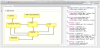
A generic software architecture enables easy and quick code development independent of platform. Many available hardware platforms can be used to implement the proposed architecture. It will provide interfaces to different devices and isolate applications from the details to increase reusability. In particular, a generic software architecture model for a vision system that works in a structured environment can be derived from a comprehensive study of traditional vision systems. Figure 1 shows a high-level diagram of such architecture.
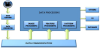
Components to be supplied by users can be identified from functional requirements and the architectural guidelines mentioned above:
-
Retrieve the data from sources.
Sources produce image data. There are a wide variety of devices and other media (e.g. cameras, video files, range scanners, etc.) that could be used as sources of image data. The data capture module addresses the task of obtaining data from these devices.
-
Convert the data in a standard format.
Different sources employ a large variety of data formats to represent the image data. In order for modules to communicate data effectively, they need to agree on the transmitted data types. The data converter module addresses allows the communication between devices with different native representations of image data.
-
Deliver the data from sources to modules in charge of performing
the processing.
In many vision systems, the components of the system are often distributed over a network or physically connected to several machines via a communication medium such as a bus. The data communication module addresses the need for inter-communication of data and control amongst the different modules of the vision system and provides methods for communication configuration.
-
Data processing.
The data processing module performs the tasks of data manipulation and analysis. We can typically identify the following components in this subsystem:
-
Image Processing.
This module is responsible for performing transformations to enhance images. The changes may include, for example, an image compression that reduces the size in memory, or an enhanced restoration of these images to improve their quality (noise removal, contrast enhancement, brightness, etc.).
-
Feature Processing.
The function of this module is feature extraction of any of the objects in the image (color, shape, size, texture, etc.).
-
Pattern Recognition.
The task of this module is the classification of objects (expressed as a vector of features) from a set of labeled patterns (vectors containing the typical values of the characteristics for each class of objects).
-
Image Processing.
- Deliver the output from processing module to other module in charge of storing, displaying or using the output for any other purpose.
Again, the communication module performs the task of data communication between various components of the vision system. In this case, it communicates the processing module to the database manager or the user interface.
The functionality associated with the described architecture must be integrated into a new architecture for vision systems working in unstructured environments. Additional functional requirements increase the complexity of vision systems working in these environments. Frequently, this complexity prevents the development of systems with suitable features to be integrated into real-time control systems (autonomous vehicles, mobile robots, etc.).
To ensure compliance with all requirements, ViSel-TR is based on the choice of a number of variables that are independent of the visual information captured by the cameras, like the robot position coordinates (GPS), meteorological information and time, etc. With this new approach, the vision system will be capable of processing visual information in real-time because the selected scenario is previously known. Thus, the first objective of ViSel-TR can be achieved: efficient interpretation and reasonable response time in an unstructured environment. To achieve the second objective (use different development paradigms offered by software engineering that allow their integration in real-time systems), we propose the use of the MDSD paradigm for separating the description of componentbased applications from their possible implementations for different platforms. C-Forge [12] is a tool-chain that combines these and others paradigms of the software engineering so it is used in this work as is shown in section 4.
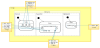
Taking into account the requirements of computer vision applications that must work in unstructured environments, the proposed software architecture is shown in Figure 2.
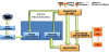
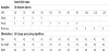
The application now works as follows. At any time, the vision system can receive a command from a user interface or from another module of the control system where vision system is integrated. Once the system has received a command, the vision system will start searching different objects. For this, it samples the information captured by sensors (GPS, lighting, temperature, humidity, etc.) through a selective filter.This information, which is independent of visual information extracted from the images captured by the cameras, is used to select the most suitable set of algorithms for processing the image according to the environment conditions. For instance, we use different algorithms for identifying road speed limit signs depending on the illumination conditions (algorithm type 1 and type 2 in Table 1). We also employ GPS coordinates to only look for objects that can appear in the place where we are. For instance, if we are in a road, we will only look for signs of speed limit lesser than 90 km/h. As shown in Figure 2, the selective filter accesses the databases to recover all the aforementioned information and controls the behavior of the feature processing and matching modules. Thus, the selective filter allows to perform two tasks: (1) select the algorithms for image processing as above mentioned (A1, A2 or A3 see Table 1), and (2) inform the matching module the database where it must search the features objects. Table 1 shows all relations of ViSiT to carry out the configuration of feature processing and matching modules to detect speed limit signs. The configurations shown in Table 1 only use two variables: illumination and GPS.
The feature processing module extracts a signature of the objects found in the image by applying the algorithms previously selected by the selective filter, depending on the environment conditions. Afterwards, the matching module compares between the vector of features extracted from the image after the processing step, and the feature vector of the candidate objects stored in the database. These candidate objects are chosen by the selective filter according again to the environment conditions.
4. A Case Study: Incremental Development Of A Selective Vision System For Cataloguing And Maintenance Of Road Elements
The real case study in which the ViSel-TR will be validated consists of a selective vision system for cataloguing road signals in order to facilitate the performing of maintenance operations. Such system will be integrated in a vehicle's control system. Briefly, the system (see Figure 3):
- Operates onboard a vehicle and interacts in real-time with its control system,
- Detects road elements in different environmental conditions (traffic signals, semaphores, crosswalk, etc.),
- Classifies and records these items based on local and global variables,
- Detects the deterioration or the absence of road elements, and Generates status reports.
In this system two operating modes are defined:
-
Cataloguing mode.
Vision system finds road elements in the images captured by a camera using a library of image processing functions. Once found a road element, its feature vector is stored in a database. This vector is composed by different parameters: some proceed from the images processing and others proceed from the information proportioned by the selective filter. This information includes data from different sensors as LIDAR, GPS, accelerometers, etc. The system will generate reports of detected elements in each mission. Such reports will include relevant information for road maintenance as the number of elements and their classification, position, size, weather condition, etc.
-
Maintenance mode.
The system will compare the road elements detected with the road elements recorded in the database during the cataloguing. The system will generate a report of the status of such elements and will inform the user if it needs some maintenance task.
The development of the case study will be performed incrementally. We have implemented increasingly complex scenarios that incorporate additional functionality, new components and interactions between them. The scenarios are the following:
-
Scenario 1, vision system detects and identifies traffic signals. To
implement this first scenario the different components incorporated
offer the following functionality:
- Ability to enter simple orders (start, stop, etc.).
- Ability to gather sensory information representing local variables (speed, acceleration, etc.) and global variables (GPS, lighting, climate, etc.).
- Ability to select data from local and global variables that are independent by filtering information.
- Ability to process images as any vision system.
- Ability to generate and access to databases for cataloguing and maintenance of road elements.
- Ability to identify road elements and generate status reports.
- Scenario 2, the system can find new objects in its environment. In particular, the ability to detect and identify cars was incorporated. In this way, the number of shapes, size and type of movements of the different objects is increased and consequently some components can increase their complexity. In particular, the images processing module could be reconfigured depending the local or global information.
- Scenario 3, which introduces new movements by means of incorporating models to the database in order to identify humans. Furthermore, the images processing module has ability to learn based on information of the different previous missions.
- Scenario 4, in which was incorporated the ability of detecting the cataloged objects when they can be degraded and finding nonidentified objects. The system performs the catalogation of new objects in databases in order to a further analysis.
-
Scenario 1, vision system detects and identifies traffic signals. To
implement this first scenario the different components incorporated
offer the following functionality:
5. A Case Study Implementation With C-Forge
The four scenarios described in this section have been implemented using C-Forge [12]. As above mentioned, C-Forge is an Eclipsebased model-driven tool-chain for supporting a component-based development process that relies on:
- A component model WCOMM (White-box COmponent Meta- Model) for modeling applications by means of components, ports and connections among them, where component behavior is expressed as finite state-machines. The main features of WCOMM, like communication among components, messages, interfaces, data-types, types of components, activities, etc., are described in [12].
- A component framework (FraCC) that provides the runtime support for executing the component-based application modeled with WCOMM. FraCC stands for Framework for Concurrent Components, since its main characteristic is that it provides user with full control over concurrency features of the application (number of processes, threads and computational load assigned to each thread). That is, FraCC provides control over the deployment of the application. FraCC has been developed in C++ and integrated into C-Forge.
Taking into account the application requirements, the application developer designs the specific application using the architectural component-oriented modeling language WCOMM. WCOMM comprises three kind of models: textual definition of the interfaces, datatypes, and activities of the applications, graphical modeling of simple components (with structure and behavior), and graphical definition of the application architecture by connecting ports of simple components. WCOMM enables users to define in different files (models) different aspects of the application. This loose coupling allows different developers work in different aspects of the system. Figure 4 shows a screen-shot of the first and last kind of WCOMM models, while figure 5 shows the definition of the Filter component as a white-box.
Once the application has been modeled, the developer executes the associated model transformations in order to generate a FraCC deployment model. This transformation configures FraCC with default parameters that can be modified by the application developer, i.e., the default assignation of concurrent regions to threads, and hides the framework implementation complexity from the user. FraCC provides explicit control over concurrency, mainly the number of processes and threads, their computational load and timing characteristics, which can be easily modified e.g. after temporal analysis. Unlike most frameworks, these tasking issues are very important in order to be able to perform real-time analysis later. FraCC also facilitates the integration of existing algorithms by allowing users to develop each of the component activities (with the algorithms) separately from the framework.
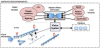
Figure 6 shows a screen-shot of a feasible deployment configuration for the WCOMM application, where the components are deployed into two computational nodes, one for executing the components related to computer vision tasks, while the other is in charge of the GUI, Filter and Non-Visual Sensors components. One node comprises one process with two execution threads, while the other isolates the execution of the GUI from the rest of the assigned components. It can also be seen that the three regions of the Filter component will be executed by the same thread, though FraCC does not impose that all the regions of a component are executed by the same thread. It does only impose that all the regions of a component must be executed by threads belonging to the same process.
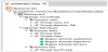
Once the FraCC model is finished, the application is executed by automatically instantiating both the WCOMM and FraCC models by a model loader. Instead of generating final code, a model loader is in charge of reading directly the WCOMM models and interpreting the components definitions that will be automatically created, and connected in FraCC processes and threads. Thus, the models are interpreted (being FraCC and their associated tools the interpreter), and they may evolve independently of the code of the algorithms.
FraCC was developed to be mostly used for the development of applications with concurrency and hard real-time requirements and was designed so that applications implemented with it could be temporally analyzed. Taking the FraCC model of a specific application as starting point, a temporal model can be extracted by an automatic transformation. This model enables an early verification of concurrency and temporal requirements using the Cheddar analysis tool [37]. The user can modify the application deployment (the FraCC model) after performing a temporal analysis without changing the original WCOMM design.
For developing the four scenarios mentioned, we have used as platform VEGO (Figure 7). VEGO is a autonomous vehicle developed by the Technical University of Cartagena and it is used to teaching and research tasks. VEGO is composed of three subsystems: (1) a sensors subsystem which include: a LIDAR sensor that it supplies the capacity to detect objects by means, an Inercial Measurement Unit (IMU) for positioning and navigation tasks, a set of ultrasonic sensors located around the vehicle they are used to detect objects in short distances, etc, (2) onboard computer subsystem which main function is to execute the software subsystem with RT capacities, for this purpose we used WxWorks operating system, and (3) the software subsystem is used to implement ViSelTR architecture.

6. Conclusions
In this work, a novel approach for developing vision systems has been presented and the main objectives have been achieved thanks to the design of a general architecture for use of different development paradigms offered by software engineering. Conclusions from this work can be drawn from two points of view: that of the benefits obtained in terms of software development (component modeling and reuse), software execution and configuration; and that of the performance benefits obtained in computer vision applications working on unstructured environments.
C-Forge combines two software engineering paradigms: component-based software development (CBSD) and model-driven software development (MDSD).
With C-Forge, the application developer designs the application using an architectural component-oriented modeling language, WCOMM, that helps him model component behavior by using finite-state machines. These components can be reused in the same or different application, and finite-state machines are very suitable for modeling reactive systems. Both elements provide designers high-level primitives with which to model their application, without worrying about the number of classes or methods that should be created to execute it. That will come in a further step. Also, both elements can be easily edited and changed through the provided graphical editors. Once the application has been modeled, the developer executes the associated model transformations and a FraCC model is generated so that the application can be executed. Thus, thanks to C-Forge, ViSel- TR separates component design (architecture, WCOMM model) from application execution (deployment, FraCC model) and the user can modify the application deployment after performing a temporal analysis without changing the WCOMM model. In fact, we were able to develop several versions of the application components quickly by reusing previous designs and slightly modifying their ports and states.
On the other hand, as mentioned before, ViSel-TR is based on the definition of scenarios in which the system can be. The approach ensures compliance with all requirements and the choice of each scenario depends on a number of variables that are independent of the visual information captured by different cameras. With this idea, the vision system is capable of processing visual information in realtime because the selected scenario is previously known, and thus it is possible to select the set of objects the system must look for, as well as the algorithms (and their configuration parameters) that are most appropriate to detect them depending on the environment conditions. In our tests, this resulted in a reduction of around 30% objects to be searched for in the images taken by the cameras, and a higher rate of detection, since the algorithms were tailored to the outdoor lighting conditions.
Thus, we can conclude that the main objectives of ViSel-TR have been achieved: our vision applications are very efficient and, furthermore, the components reusability has been incremented. ViSel-TR has demonstrated its effectiveness in improving software productivity and quality.
7. Future Works
We envisage conducting an evaluation of the approach and C-Forge toolset involving professional software developers, once the tools are more tightly integrated and tested.
Currently, there are other technologies can be considered for developing computer vision applications. Over the last couple of years, the Internet of Things and Services (IoTS) is offering new possibilities for environmental information sensing, processing and analysis by mean of connecting intelligent devices, thereby making way to new automation and control applications and services in numerous sectors [38]. All sectors where IoTS has been applied share the common aim of increasing efficiency, reducing costs, improving decision making, saving energy and protecting the environment [39].
Therefore, vision systems, which use information from different sensors in order to identify objects, are an interesting field to take advantage of in IoTS applications. The miniaturization of such sensors, together with the expansion of communication networks, have enabled intelligence and connectivity to be incorporated into real-world objects. Thus, any object can be a source of data and its behavior can be monitored in real time. Furthermore, business is clearly starting to invest in smart services. Increasingly, companies are turning to external providers who can offer powerful solutions based on shared service centers that allow their clients to get on with their core business. There is a wide variety of service providers (data storage, Web Services, etc.) among which it should be noted Google App Engine [40]. This option has the disadvantage of requiring the use of proprietary software. Google App Engine is in full growth and has the advantage of lower prices, provides useful additional services such as searches and image treatment, etc.
Other interesting alternative in which we are currently working on is the FI-WARE project in Europe: an open challenge to dedicated core Future Internet (FI) technology [41]. FI-WARE is being developed as part of the Future Internet Public Private Partnership (FI-PPP) program launched by the European Commission in collaboration with the ICT Industry. This platform aims to facilitate the creation of innovative applications by lowering the costs and complexity of serving large numbers of users globally and handling data at a large scale.
FI-WARE is open [42] and based upon Generic Enablers (GEs) which offer reusable and commonly shared functions serving a multiplicity of Usage Areas across various sectors. The platform offers a catalogue in which you will find all the information you need as a developer to start using a Generic Enabler Implementation. Some of the Generic Enablers implementations that are present in the FI-WARE catalogue are grouped into the following domains of knowledge: (1) Applications&Services, (2) Cloud Computing, (3) Internet of Things, (4) Data Context Management, (5) Interface to Networks and Devices, and (6) Security. Using FIWARE, some GEs can implement different WCOMM model components.
Competing Interests
The authors declare that they have no competing interests.