


1. Introduction
The application of nuclear power plants as a source of process heat has received national interest because of better economics without greenhouse gases. The Next Generation Nuclear Plant (NGNP) will most likely be producing electricity and process heat, used for hydrogen production. The process heat applicability is not restricted to hydrogen production, but also various other technologies such as extraction of iron ore, coal gasification and liquefactions, etc. For process heat, a thermal device is needed in order to transfer the thermal energy from the NGNP to the hydrogen plant in the most efficient way possible. Heat pipes have been recognized for several years as very effective heat transport device. They transport large amount of heat with small temperature gradients independent of gravity effects. Heat Pipe (HP) [1] is a device of very high thermal conductance, which came into existence in early 1942 [2], but the important features of a heat pipe were not realized until 1960s.
For process heat, Intermediate Heat Exchangers (IHX) [3] are required to transfer heat from the NGNP to the hydrogen plant in the most efficient way possible. The production of power at higher efficiency using Brayton Cycle, and hydrogen production requires both heat at higher temperatures (up to 10000C) and high effectiveness compact heat exchangers to transfer heat to either the power or process cycle. The purpose for selecting a compact heat exchanger is to maximize the heat transfer surface area per volume of heat exchanger; this has the benefit of reducing heat exchanger size and heat losses. The IHX design requirements are governed by the allowable temperature drop between the outlet of the NGNP (9000C, based on the current capabilities of NGNP), and the temperatures in the hydrogen production plant. Spiral Heat Exchangers (SHE’s) have superior heat transfer characteristics and are less susceptible to fouling. Further, heat losses to surroundings are minimized because of its compact configuration. SHEs have never been examined for phase-change heat transfer applications. The research presented provides useful information for thermosyphon design and Spiral Heat Exchanger [4].
Furthermore, in recent years a lot of attention and consideration has been give to usage of heat pipe for this purpose by many researches including this author [5].
In this white paper we are summarizing some of heat pipe application for purpose of driving heat process for fissionable nuclear reactors giving new attention to Generation-IV of these power plants if form of Small Modular Reactor (SMR) [6] in past one decade and in particular the advanced type of this generation at the hightemperature of the required operation and specification. Such reactors are very important if we are seeking for higher and enhanced thermal output efficiency near gas-turbine type generating electricity.
As we stated in above, the production of power in Next Generation Nuclear Plant (NGNP) at higher efficiency using Brayton Cycle, requires high-temperature operating envelope [7].
2. Heat Pipe Description
A heat pipe is a two phase heat transfer device with a very high effective thermal conductivity. It is a vacuum tight device consisting of an envelope, a working fluid, and a wick structure. As shown in Figure-1, the heat input vaporizes the liquid working fluid inside the wick in the evaporator section. The saturated vapor, carrying the latent heat of vaporization, flows towards the colder condenser section. In the condenser, the vapor condenses and gives up its latent heat. The condensed liquid returns to the evaporator through the wick structure by capillary action. The phase change processes and two- phase flow circulation continue as long as the temperature gradient between the evaporator and condenser are maintained. See Figure 1.

Heat pipes function by absorbing heat at the evaporator end of the cylinder, boiling and converting the fluid to vapor. The vapor travels to the condenser end, rejects the heat, and condenses to liquid. The condensed liquid flows back to the evaporator, aided by gravity. This phase change cycle continues as long as there is heat (i.e. warm outside air) at the evaporator end of the heat pipe. This process occurs passively and there is no external electrical energy required.
At the hot interface of a heat pipe a liquid in contact with a thermally conductive solid surface turns into a vapor by absorbing heat from that surface. The vapor then travels along the heat pipe to the cold interface and condenses back into a liquid – releasing the latent heat. The liquid then returns to the hot interface through either capillary action, centrifugal force, or gravity, and the cycle repeats. Due to the very high heat transfer coefficients for boiling and condensation, heat pipes are highly effective thermal conductors. The effective thermal conductivity varies with heat pipe length and can approach 100 kW/ (m•K) for long heat pipes, in comparison with approximately 0.4 kW/ (m•K) for copper.
Heat pipes employ evaporative cooling to transfer thermal energy from one point to another by the evaporation and condensation of a working fluid or coolant. Heat pipes rely on a temperature difference between the ends of the pipe and cannot lower temperatures at either end below the ambient temperature (hence they tend to equalize the temperature within the pipe). Figure 2.

Heat pipes have an envelope, a wick, and a working fluid. Heat pipes are designed for very long term operation with no maintenance, so the heat pipe wall and wick must be compatible with the working fluid. Some material/working fluids pairs that appear to be compatible are not. For example, water in an aluminum envelope will develop large amounts of non-condensable gas over a few hours or days, preventing normal operation of the heat pipe.
2.1 Heat pipe materials and working fluids
Since heat pipes were rediscovered by George Grover in 1963 and the result was published in 1964 [8], an extensive life tests have been conducted to determine compatible envelope/fluid pairs, some going on for decades. In a heat pipe life test, heat pipes are operated for long periods of time, and monitored for problems such as non-condensable gas generation, material transport, and corrosion.
2.2 Different type of heat pipes
In addition to standard, Constant Conductance Heat Pipes (CCHPs), there are a number of other types of heat pipes, including [1]:
- Vapor Chambers (planar heat pipes), which are used for heat flux transformation, and isothermalization of surfaces
- Variable Conductance Heat Pipes (VCHPs), which use a Non- Condensable Gas (NCG) to change the heat pipe effective thermal conductivity as power or the heat sink conditions change
- Pressure Controlled Heat Pipes (PCHPs), which are a VCHP where the volume of the reservoir, or the NCG mass can be changed, to give more precise temperature control
- Diode Heat Pipes, which have a high thermal conductivity in the forward direction, and a low thermal conductivity in the reverse direction
- Thermosyphons, which are heat pipes where the liquid is returned to the evaporator by gravitational/accelerational forces,
- Rotating heat pipes, where the liquid is returned to the evaporator by centrifugal forces
2.3 Benefits of heat pipe device
- High Thermal Conductivity (10,000 to 100,000 W/m K)
- Isothermal
- Passive
- Low Cost
- Shock/Vibration tolerant
- Freeze/thaw tolerant
2.4 Limitations of heat pipe device
- Heat pipes must be tuned to particular cooling conditions. The choice of pipe material, size and coolant all have an effect on the optimal temperatures at which heat pipes work.
- When used outside of its design heat range, the heat pipe's thermal conductivity is effectively reduced to the heat conduction properties of its solid metal casing alone - in the case of a copper casing, around 1/80 of the original flux. This is because below the intended temperature range the working fluid will not undergo phase change; and above it, all of the working fluid in the heat pipe vaporizes and the condensation process ceases.
- Most manufacturers cannot make a traditional heat pipe smaller than 3 mm in diameter due to material limitations.
3. Intermediate Heat Exchanger (IHX)
The NGNP is intended to increase energy efficiency in electricity production primarily by exchanging the steam power cycle for the Brayton power cycle. Overall thermal efficiency should increase to approximately 50% (Fisher and Sindelar 2008) [9]. The Brayton cycle operates at higher temperatures than the steam cycle and offers the opportunity to use some of the plant’s energy to produce hydrogen in addition to electrical power. The production of power at higher efficiency using the Brayton Cycle [7] and hydrogen production require both heats, at higher temperatures up to 1,300 K, and highly effective Compact Heat Exchangers (CHEs) [4] to transfer heat to either the power or process cycle. Today’s CHEs provide very efficient heat transfer (>95%) (Fisher and Sindelar 2008) [9] and approach the operating temperature of the Brayton cycle. Thus, they are ideal candidates for service in the NGNP. Very efficient heat transfer from primary to secondary fluid loops is critical to the NGNP concept and the purpose in selecting a CHE was to maximize the heat transfer surface area per volume of heat exchanger. It has the benefit of reducing heat exchanger size, making it more economical from a materials-of-construction and facility footprint perspective. However, the demands of the high temperature Brayton cycle challenge the boundaries of existing heat exchanger technology for service in nuclear systems. Irrespective of the NGNP reactor type (prismatic core or pebble bed) and the resultant coolant, the key to high efficiency is a high effectiveness heat exchange. Efficient design of the Intermediate Heat Exchanger (IHX) is critical for effective utilization of the energy generated in the NGNP, therefore a CHE is chosen. The design of the intermediate heat exchanger requires reconciling a large number of considerations, primarily including:
- CHE to improve safety and economics.
- Achieving the required thermal effectiveness (boundary temperature limitation for efficient heat transfer to hydrogen plant) at minimal pressure drop.
- Choosing suitable materials for construction to address the high temperature and corrosion issues.
- Ensuring valid mechanical design and sustainability at a high operating temperature.
CHEs are characterized by large surface area-to-volume ratios; 300 m2/m3 to greater than 3,000 m2/m3 are available (counts all area exposed to working fluid, Fisher and Sindelar 2008). Their large surface area-to-volume ratio indicates small flow passages. This, in turn, indicates large resistance to flow, which may increase further by surface contours designed to enhance turbulence within the flow channels. The flow paths of CHEs are kept short to lower operating pressures and reduce stress on materials of construction (Fisher and Sindelar 2008) [9].
4. Heat Pipe Applications
As we stated in description of heat pipe,
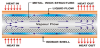
A heat pipe is a passive energy recovery heat exchanger that has the appearance of a common plate-finned water coil except the tubes are not interconnected. Additionally, it is divided into two sections by a sealed partition. Hot air passes through one side (evaporator) and is cooled while cooler air passes through the other side (condenser). While heat pipes are sensible heat transfer exchangers, if the air conditions are such that condensation forms on the fins there can be some latent heat transfer and improved efficiency. See Figure 3.

Heat pipes are tubes that have a capillary wick inside running the length of the tube, are evacuated and then filled with a refrigerant as the working fluid and are permanently sealed. The working fluid is selected to meet the desired temperature conditions and is usually a Class I refrigerant. Fins are similar to conventional coils - corrugated plate, plain plate, spiral design. Tube and fin spacing are selected for appropriate pressure drop at design face velocity. HVAC systems typically use copper heat pipes with aluminum fins; other materials are available.
3.1 Nuclear power conversion
Grover and his colleagues were working on cooling systems for nuclear power cells for space craft, where extreme thermal conditions are encountered. These alkali metal heat pipes transferred heat from the heat source to a thermionic or thermoelectric converter to generate electricity.
Since the early 1990s, numerous nuclear reactor power systems have been proposed using heat pipes for transporting heat between the reactor core and the power conversion system. The first nuclear reactor to produce electricity using heat pipes was first operated on September 13, 2012 in a demonstration using flattop fission.
In Nuclear power plant application, heat pipes can be used as a passive heat transfer system for performing as overall thermal hydraulic and natural circulation sub-system in an Inherent Shutdown, Heat Removal System (ISHRS) in the core (i.e. installed on top of the core doom) of nuclear reactor such as Molten Salt or Liquid Metal Fast Breeder type reactors, as a secondary fully inherent shutdown system loop acting like heat exchanger from safety point of view so the reactor never reaches to its melting point in case of accidental events.
The waste heat recovery driven by heat pipes has been suggested and is accepted as an excellent way of saving energy and preventing possible global warming, while they can be used as part of heat exchanger infrastructure. Heat pipe application as part of sub-system in heat exchangers for the heat recovery is focused on the energy saving and the enhanced effectiveness of the Conventional Heat Pipe (CHP) [1,7], Two-Phase Closed Thermosyphon (TPCT), yet one-dimensional analysis and Oscillating Heat Pipe (OHP) [1] heat exchangers. Thus, we go into the required parameters of effectiveness of the CHP, TPCT and OHP heat exchangers and start to describe them, we need to have some general understanding of heat pies and what they are, however more details can be found in refence by Zohuri [1].
Heat pipes are becoming increasingly popular as passive heat transfer technologies due to their high efficiency. A heat pipe is a passive energy recovery heat exchanger that has the appearance of a common plate-finned water coil except the tubes are not interconnected. Additionally, it is divided into two sections by a sealed partition. Hot air passes through one side (evaporator) and is cooled while cooler air passes through the other side (condenser). While heat pipes are sensible heat transfer exchangers, if the air conditions are such that condensation forms on the fins there can be some latent heat transfer and improved efficiency.
There are some pros and cons involved with usage of the heat pipeas a heat transfer device and has the following Advantages and Disadvantages:
3.1.1 Advantages
- Passive heat exchange with no moving parts,
- Relatively space efficient,
- The cooling or heating equipment size can be reduced in some cases,
- The moisture removal capacity of existing cooling equipment can be improved,
- No cross-contamination between air streams.
3.1.2 Disadvantages
- Adds to the first cost and to the fan power to overcome its resistance,
- Requires that the two air streams be adjacent to each other,
- Requires that the air streams must be relatively clean and may require filtration.
3.2 Heat pipe application as heat exchanger
Heat pipe heat exchanger enhancement can improve system latent capacity. For example, a 10 F dry bulb drop in air entering a cooling coil can increase the latent capacity by about 3%. Both cooling and reheating energy is saved by the heat pipe's transfer of heat directly from the entering air to the low-temperature air leaving the cooling coil. It can also be used to precool or preheat incoming outdoor air with exhaust air from the conditioned spaces.
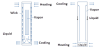
Heat Pipe Heat Exchangers are custom built to accurately meet and exceed customer expectations and can be designed with proportional control to operate in conjunction with the climate control system. The use of the heat pipe as a component in a heat recovery device has gained worldwide acceptance. Heat pipes are passive, highly reliable and offer high heat transfer rates due to the nature of heat pipe infrastructure. As we briefly describe in above and details can be found in refence by Zohuri [1], A heat pipe is a thermodynamic device which transfers thermal energy from one location to another with a very small temperature drop. Figure 1 illustrates a conventional heat pipe with three sections as it can be seen in Figure 4:

- The evaporator section where heat is added to the system;
- The condenser section where heat is removed from the system; and
- Adiabatic section which connects the evaporator and the condenser.
In recent years, considerable interest has been generated regarding the heat pipe heat exchanger as a heat recovery system. The heat pipe is a relative newcomer to the field of heat transfer, and its full potential is yet to be appreciated, especially in its application as Heat Pipe Heat Exchanger (HPHE). Heat pipes are ideally suited for many waste heat recovery applications because of their ability to act as thermal flux transformers, their low maintenance, and their ability to achieve an isothermal surface of low thermal impedance. Heat pipe units can provide design flexibility when waste heat recovery systems are planned, and they can be utilized when retro-fitting to existing systems. Figure 5 is depiction of heat pipe driving heat exchanger application.
Heat Pipe Heat Exchangers are driven by the classifications of heat pipe driving heat recover systems and it is possible to classifying them as four main applications as demanded for waste heat recovery apparatus.
Heat pipes are ideally suited for many waste heat recovery applications. Heat pipe units can provide design flexibility when waste heat recovery systems are planned, and they can be utilized when retro-fitting to existing systems. The different heat pipe heat exchangers are described below [10]:
- gas-to-gas,
- gas-to-liquid,
- liquid-to-gas,
- liquid-to-liquid.
Application of each of the above categories can be found in Reference by Azad.
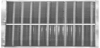
Azad et al. [11] reported a theoretical analysis of the multi-stage Heat Pipe Heat Recovery System (HPHRS). In this study, thermal performance and temperature profile in the flow direction of both evaporator and condenser sections of the HPHRS were developed. This study presents the heat transfer characteristics of different arrangement of a HPHRS. In this study, thermal performance and temperature profile in the flow direction of both evaporator and condenser sections of the HPHRS are presented in Figures-6(a) and (b) and 7(a) and 7(b).
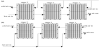

In multi-stage heat pipe heat exchanger, the system contains several units. Each individual unit is a heat pipe heat exchanger and they operate independently. The behavior of multi-stage heat pipe heat exchanger, with flow in series in the condenser sections and parallel in the evaporator sections of the units (Fig11(a)), or in condenser sections the flows are in parallel and in series in the evaporator sections (Figure-6(b)), differs from that at a conventional heat pipe heat recovery system. Its performance depends on among other factors, the number of stages and distribution of hot and cold fluid.
3.3 Best applications
- Where lower relative humidity is an advantage for comfort or process reasons, the use of a heat pipe can help. A heat pipe used between the warm air entering the cooling coil and the cool air leaving the coil transfers sensible heat to the cold exiting air, thereby reducing or even eliminating the reheat needs. Also, the heat pipe precools the air before it reaches the cooling coil, increasing the latent capacity and possibly lowering the system cooling energy use.
- Projects that require a large percentage of outdoor air and has the exhaust air duct in close proximity to the intake, can increase system efficiency by transferring heat in the exhaust to either precool or preheat the incoming air.
3.4 Possible applications
- Use of a dry heat pipe coupled with a heat pump in humid climate areas.
- Heat pipe heat exchanger enhancement used with a single-path or dual-path system in a supermarket application.
- Existing buildings where codes require it or they have "sick building" syndrome and the amount of outdoor air intake must be increased,
- New buildings where the required amount of ventilation air causes excess loads or where the desired equipment does not have sufficient latent capacity.
5. Technology Types/Resources
Hot air is the heat source, flows over the evaporator side, is cooled, and evaporates the working fluid. Cooler air is the heat sink, flows over the condenser side, is heated, and condenses the working fluid. Vapor pressure difference drives the evaporated vapor to the condenser end and the condensed liquid is wicked back to the evaporator by capillary action. Performance is affected by the orientation from horizontal. Operating the heat pipe on a slope with the hot (evaporator) end below horizontal improves the liquid flow back to the evaporator. Heat pipes can be applied in parallel or series.
6. Efficiency
Heat pipes are typically applied with air face velocities in the 450 to 550 feet per minute range, with 4 to 8 rows deep and 14 fins per inch and have an effectiveness of 45% to 65%. For example, if entering air at 77 °F is cooled by the heat pipe evaporator to 70 °F and the air off the cooling coil is reheated from 550F to 650F by the condenser section, the effectiveness is 45 % [=(65-55)/(77-55) = 45%]. As the number of rows increases, effectiveness increases but at a declining rate. For example, doubling the rows of a 48% effective heat pipe increases the effectiveness to 65%.
Tilt control can be used to:
- change operation for seasonal changeover,
- modulate capacity to prevent overheating or overcooling of supply air,
- decrease effectiveness to prevent frost formation at low outdoor air temperatures.
Tilt control (6 maximum) involves pivoting the exchanger about its base at the center with a temperature-actuated tilt controller at one end. Face and bypass dampers can also be used.
7. Heat Pipes and Thermosyphon
The heat pipe shown in Figure 8 is essentially a constant temperature, heat transfer device. It consists of a closed container in which vaporization and condensation of a fluid takes place. The choice of a fluid depends on the temperature range in which the heat pipe will be used. Heat is applied to one end of the heat pipe (evaporator), which raises the local temperature leading to evaporation of the working fluid.
Because of the saturation conditions this temperature difference results in a difference in vapor pressure, which in turn causes vapor to flow from the heated section to the cold section of the pipe (condenser). The rate of vaporization is equal with heat absorbed in the form of latent heat of evaporation. The resulting condensate is returned to the heated end (evaporator) of the container by the action of capillary forces in the liquid layer, which is contained in a wick lining inside the cavity. A typical wick might consist of layers of metal screen or some porous metallic structure. A wick is used in the heat pipes to return the working fluid from the condenser to the evaporator.
Wicking material is used in regions to facilitate the path of the vapor to the pipe. Typically, a good wicking material maximizes the movement of the fluid, has uniform porosity, has very small pores such that the wick can generate a large capillary pressure, is resistant to degradation by temperature, and does not react or degrade chemically with the working fluid. Heat pipes can have a number of different geometric configurations. These configurations include cylindrical, spherical, square, or any other geometry such that inner volume of the heat pipe forms a channel from the evaporator section to the condenser section. Metals used to fabricate the heat pipes should be compatible with the working fluid as well as with the external media in contact with the evaporator and the condenser. The outermost shell of the heat pipe is referred to as the container. The container encloses the functioning parts of the heat pipe and provides structural rigidity. The liquid flow takes place in a porous material usually referred to as wick. The interior space of the heat pipe is called the vapor core, which provides passage for the vapor flow. Heat pipes have been used extensively in a variety of energy storage systems such as chemical reactors and space craft temperature equalization. Heat pipes are well suited to thermal storage systems, particularly in the roles of heat delivery and removal, because of their highly effective thermal conductivity and passive operation.
8. Direct Reactor Auxiliary Cooling System (DRACS)
Historically, the idea of implementing a loop known as Direct Reactor Auxiliary System (DRACS) as a passive heat removal system in a nuclear power plant for safety purpose is nothing new. The DRAC system originally was derived from the Experimental Breeder Reactor- II (EBR-II), and then it was improved in later fast reactor designs such as Clinch River Breeder Reactor Project (CRBRP) by Westinghouse around 1970’s time frame on their Liquid Metal Fast Breeder Reactor (LMFBR) and then later on was manufacture for French reactor known as Phoenix-II, which went into operation in France.
The DRACS has been proposed for Advance High Temperature Reactor (AHTR) as the passive decay heat removal system. The DRACS features three coupled natural circulation/convection loops relying completely on buoyancy as the driving force. In the DRACS, two heat exchangers, namely, the DRACS Heat Exchanger (DHX) and the Natural Draft Heat Exchanger (NDHX) are used to couple these natural circulation/convection loops. In addition, a fluidic diode is employed to restrict parasitic. In addition, a fluidic diode is employed to restrict parasitic flow during normal operation of the reactor and to activate the DRACS in accidents.
While the DRACS concept has been proposed, there are no actual prototypic DRACS systems for AHTRs built and tested in the literature. In this report, a detailed modular design of the DRACS for a 20-MWth Fluoride Salt Cooled High Temperature Reactor (FHR) is first developed. As a starting point, the DRACS is designed to remove 1% of the nominal power, i.e., the decay power being 200 kW.
The design process for the prototypic DRACS involves selection of the salts, identification of the reactor core, design of the DHX and NDHX, design of the fluidic diode, design of the air chimney, selection of the loop pipes, and finally determination of the loop height based on pressure drop analysis. FLiBe with high enrichment in Li-7 and FLiNaK have been selected as the primary and secondary salts, respectively. A 16-MWth pebble bed core proposed by University of California at Berkeley (UCB) is adopted in the design. Shell-and-tube heat exchangers have been designed based on Delaware Method for the DHX and NDHX.
A vortex diode that has been tested with water in the literature is adopted in the present design. Finally, pipes with inner diameter of 15 cm are selected for both the primary and secondary loops of the DRACS. The final DRACS design features a total height less than 13 m. The design presented here has the potential to be used in the planned small-scale FHR test reactor and will also benefit and guide the DRACS design for a commercial AHTR.
Following the prototypic DRACS design is the detailed scaling analysis for the DRACS, which will provide guidance for the design of scaled-down DRACS test facilities. Based on the Boussinesq approximation used in the field of buoyancy-driven flow (i.e. also known as natural convection) in one-dimensional formulation, the governing equations, i.e., the continuity, integral momentum, and energy equations are non-dimensionalized by introducing appropriate dimensionless parameters, including the dimensionless length, temperature, velocity, etc. The key dimensionless numbers, i.e., the Richardson, friction, Stanton, time ratio, Biot, and heat source numbers that characterize the DRACS system, are obtained from the non-dimensional governing equations. Based on the dimensionless numbers and non-dimensional governing equations, similarity laws are proposed. In addition, a scaling methodology has also been developed, which consists of the core scaling and loop scaling.
9. Conclusion
This paper will provide valuable data that will be useful in making decisions regarding the heat transfer system between the nuclear reactor and chemical plant. Development of very high temperature reactor technologies for the production of hydrogen and other energy products is high priority research for a successful nuclear future and a premier role to play in the development of these technologies that are integral to the DOE strategic plans for the sustained advances in nuclear energy (Figure 9).
Overall, a heat pipe is a heat-transfer device that combines the principles of both thermal conductivity and phase transition to effectively transfer heat between two solid interfaces. Figure 10.

Phase-change processes and the two-phase flow circulation in the HP will continue as long as there is a large enough temperature difference between the evaporator and condenser sections. The fluid stops moving if the overall temperature is uniform but starts back up again as soon as a temperature difference exists. No power source (other than heat) is needed.
In some cases, when the heated section is below the cooled section, gravity is used to return the liquid to the evaporator. However, a wick is required when the evaporator is above the condenser on earth. A wick is also used for liquid return if there is no gravity, such as in NASA’s micro-gravity applications.
The success of the next generation of nuclear reactors will depend, in part, on successfully utilizing process heat and on the selection of heat transport devices, such as the thermosyphon as discussed in this chapter. For high temperature applications requiring the transport of large amounts of thermal power at a small temperature difference between the heat source and the heat sink, the thermosyphon is one option. Thermosyphon working fluids should have a high latent heat of vaporization such as found for liquid metals, which in turn makes them a preferable choice for transporting thermal energy. Although considerable data already exists on the thermophysical properties of possible working fluids, data, especially in the vapor phase, is rarely available at the high temperatures of NGNP. Accurate performance predictions of thermosyphon startup and operational behavior is required to design and build reliable and efficient systems for high temperature process heat transfer from NGNP to a hydrogen plant.
Instabilities are common in both forced and natural circulation systems; the latter is more unstable than the former. The mechanisms that can lead to unstable operational behavior of the thermosyphon have been discussed along with the importance of having active nucleation sites in the evaporator section. Due to differences in operating conditions, previous studies have resulted in diverse values of the optimum inclination angle (corresponding to the maximum heat transfer rate) for a thermosyphon, the optimum inclination angle when the heat transfer capacity reaches its maximum is reported to be around 40 degrees (Terdtoon et al. 1990). The information in this section provides insights and options useful in the design and development of an NGNP process heat recovery system using a thermosyphon.
Competing Interests
The author declare that there is no competing interests regarding the publication of this article.