


1. Introduction
Sign language is a form of communication used by the deaf and verbally-challenged community. It involves the use of hand, body parts and facial expression to express emotion and to deliver message. However, it is seldom used by the normal hearing community and as with minority languages, not many are able to understand. This poses communication barriers between the deaf community and the rest of the society, which creates a need for sign language recognition research to be conducted to bridge the communication gap.
Hand gesture and sign language recognition has been an active field of research. It can be achieved through vision-based and sensor-based approaches. Vision-based approaches collects images or video frames captured using camera as input of the system. It can be achieved using either appearance-based or model-based approaches. Appearancebased approaches uses visual cues as the recognition features. Modelbased approaches attempts to infer the posture of finger, joint angle and the palm in 2D or 3D space [1]. Sensor-based approaches involve the use of sensing devices usually to be worn by the user when performing gesture recognition. Some common sensors include the using of inertial measurement, electromyography, flex sensors and radar.
In hand gesture and sign language recognition research, some of the more commonly used techniques in segmentation of the hand region from the background is skin color segmentation [2-4]. It can easily determine the global position of the hand, and it is commonly conducted in YCbCr or HSV color space as chrominance channel are easily separated from luminance channel which allows the lighting variation factor to be diminished [5]. However, sensitivity of skin color in an image towards variation in skin color, background illumination, and other factor poses challenges [6]. More adaptive skin color segmentation and hybrid of other features can improve this problem such as training a Gaussian Mixture Model in [7,8], or dynamic skin color modelling method such as in research [9]. Some other segmentation methods include hand tracking using Continuously Adaptive Mean-Shift (CAMShift) in [10,11] and using Picture Information Measure (PIM) to quantify entropy of image in [12].
Some notable appearance-based feature extraction method includes the extraction of Shift-Invariant Feature Transform (SIFT) features from the gesture. For example, in paper [13], SIFT features are extracted from six signs and the features are rotational invariant. Research in [14,15] also extracted SIFT features from the hand gestures, and the features are simplified by first quantizing with K-means clustering and then mapped into Bag-of-Features (BoF). Representing SIFT features using BoF reduces and uniforms the dimensionality of each SIFT features extracted.
Speeded Up Robust Feature (SURF) is another notable feature extraction method proposed in [16]. The authors in paper [17] extracted SURF features from a moving hand gestures of consecutive frames, and by analyzing correlation between SURF points, classification of 26 gestures achieves 84.6% accuracy. Computational performance of SIFT and SURF has been compared in paper [15], as the extraction of features is usually a computationally heavy process and hence the efficiency of the technique plays an important role. It is showed that SURF has a faster processing speed.
Principle Component Analysis (PCA) is another commonly extracted features in hand gesture recognition research. In paper [18], PCA is extracted together with kurtosis position and chain code, where kurtosis position is used in finding edges and chain code is used in tracking the hand trajectory. The hybrid of these three features has shown to outperform any features alone with an error rate of 10.91%.
Model-based sign language recognition based on convexity defect features has been widely applied in research in this field [19-30]. The advantage of using this approach as compared to other appearance- based approaches is that the former usually does not involve computationally heavy feature extraction and training of features [23]. From these researches, it is observed that the selection of complementary features and rules that define convexity defects greatly affects the scalability and performance. In paper [19], the numbers of fingers raised in the hand gestures are extracted using convexity defects method. The author calculates the mean, standard deviation and contour area of each gesture, and Naïve Bayes classifier is used to classify five gestures. Author in [27] extracts just convexity defects features from hand gestures and multiclass SVM is used to classify 10 gestures and these results in an accuracy of 93%. In paper [25], the author utilizes convexity defects features to count the number of fingers raised and is able to identify four classes of gestures in a robot controlling application. Research in [29] also able to identify the numbers of fingers raised using convexity defects method and able to recognize six gestures with average accuracy of 95%. However, the authors in these researches did not address the identification of which finger of the hand was raised.
Some researches identify exactly which fingers are raised in a sign language, and define the palm area, fingers, and forearm from the hand gesture. In paper [22], the authors first identify palm and wrist location and by using angle information, the exact fingers that are raised can be identified. The system is also able to identify the fingers when both hands are present. However, finger identification using angle threshold is prone to misclassification when fingers are not raised vertically but with a skewed angle. In paper [20], the authors first identify the hand palm by finding minimum inscribed circle. K-curvature features is then utilized together with convexity defects to find the finger location from the hand gestures, which is able to identify nine hand gestures in real-time.
The challenges in identifying visually similar sign languages however are not addressed in previous research, such as the ASL “K” and “V”. Therefore, we further proposed a framework to use Hough Line features with features extracted using convexity defects and K-curvature to improve the separation criteria between the signs. We also proposed the utilization of finger webs feature to improve the separation criteria. Our proposed method has shown to be able to distinguish visually similar signs with high accuracy.
2. Materials and Method
2.1 System overview
The main camera of the iPhone 5s is utilized to capture video stream of American Sign Language (ASL) performed in real-time. The video camera collects frames of images in 2D RGB color space, and it does not contain depth information.
In appearance-based approaches, exhaustive number of training images are required to train the database. In model-based approach, this is not required. This proposed model-based framework focus on correctly modelling the different posture, orientation and trajectory of the ASL in 2D space. Firstly, signer’s hand’s information is obtained for calibration purpose to improve the robustness of segmentation process. The input image is then downsized for better computational efficiency. Next, skin color, edges and area information are extracted to segment the hand region from the background.
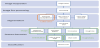
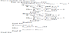
In feature extraction stage, convexity defects, k-curvature, Hough lines and several other features are extracted to determine the hand posture. The information of hand orientation is determined by calculating the palm center to wrist angle. For static finger-spelled sign, hand posture and orientation information are sufficient to classify the signs. For dynamic gestures however, trajectory motion of the gesture is extracted and quantized using chain code method. Lastly, Decision Tree classification is used to classify the spatial, orientation, and trajectory features to its respective signs. The output of the recognized sign language will then be displayed as a text and played as an audio speech. Figure 1 shows an overall algorithm flow and techniques used.
2.2 Parameter used
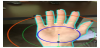
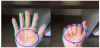
In this paper, the anatomies of hand involved in the hand recognition framework are the palm, arm, wrist, fingertips, finger webs and the finger joints as labelled in Figure 2.
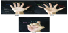
Each finger is given a color identifier as follows, thumb labelled as red color, index finger labelled as orange color, middle finger labelled as yellow color, ring finger labelled as green color and lastly pinky labelled as blue color. These color identifiers will be used throughout this research. The webbed area between fingers is referred to as the finger webs. The identification of each finger web follows the finger that precedes it in a counter-clockwise direction. For instance, in Figure 2(b), the finger web between the thumb and the index finger will be referred to as the web of the thumb and the same applies to the rest of the finger webs.
In Figure 2(c), it can be observed that the finger webs position remains the same, despite different posture of fingers. When two adjacent fingers are not raised, the small ‘valley’ of a finger web remains which serves as a useful feature which can be utilized for the recognition of the hand posture. The joint of the fingers closest to the palm is called as Proximal interphalangeal joint, however, it will be simply referred to as ‘joint’ in this paper as shown in Figure 2c.
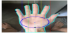
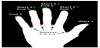
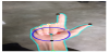
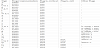
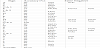
Several parameters are used throughout this paper, and these parameters and its description are summarized in Table 1. These parameters are kept constant throughout this experiment. These parameters differ across different experiment setup, such as when different signers or data acquisition camera is used. The parameter rowmax and colmax are the height and width of the input frame respectively. The value pmin is introduced to avoid redundant points detected for a single hand feature. For instance, a fingertip could have several maximum points detected, introducing pmin will eliminate points too close with each other. The optimal constant value is determined through visual observation and it is set to be relative to the radius of palm circle, rpalm so it will be scale invariant. The parameters kth, kin, kmi, and kri are introduced to define a range of horizontal distance for each different finger web. This range is used to assign each finger web point extracted to the respective finger web of the hand. kth is represented by red vertical line; kin is represented by yellow vertical line; kmi is represented by green vertical line; kri is represented by green vertical line. Lastly the white vertical line is the vertical line passing through palm center as shown in Figure 3.
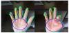
The parameters kraised, kbent, kth-raised, kpi-raised are introduced to quantize each finger to different finger posture namely not raised, half-raised and fully raised. The parameter kraised are represented by orange circular lines and the parameters kbent, kth-raised, kpi-raised are represented by green circular lines in Figure 4. The parameter kdef-dist is introduced specifically to identify the finger posture of a fully raised finger to be close-by with an adjacent finger or not. All the constant values used in these parameters are obtained through visual observation of optimal parameters which fit the hands of all five signers. The flags will be used in the algorithm later in this chapter to assign each sign or observation to a certain category which will be used as a decision factor in the Decision Tree classification. Parameter stop Frame Count is introduced to track the frames count of dynamic gestures.
2.3 Hand segmentation
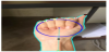
In segmentation stage, skin color, edges and area information are used to extract the hand region from the background. An adaptive segmentation method by utilizing a manual calibration process whereby skin pixel input of the signer are used to facilitate the segmentation process. A one-time calibration process is carried out to help increase the invariance towards signers’ skin tone and different background illumination. Calibration is performed to collect skin pixels values of the signer’s hand in HSV color space. The image captured is first converted into HSV color space. The pixel value obtained will be used for auto detection and segmentation of hand from the background. A red rectangular box will first be displayed on the screen as shown in Figure 5(a), and signer are prompted to place their hand covering the box area for skin pixel value extraction. The size of rectangular box used is obtained through visual observation of sizes that fits the hand in this experiment. Calibration operation can be performed again whenever the signer or the environment has been changed.
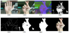
HSV color space is used as the chrominance and luminance channels are separated per sec. By ignoring the luminance channel, the variation in background illumination factor can be reduced, and thus making it suitable to be used for skin color segmentation [31]. Histogram backprojection method [32] is used to incorporate an environment adaptive segmentation. Histogram backprojection can localize a known object in a scene based on its color appearance. It uses a histogram of a known object of interest to find the ROI in the new input image that matches the color value of the histogram. It calculates and replaces all the pixels value in the new input image with the probability of the pixel belonging to the object in the histogram. Hence, histogram backprojection is suitable to be utilized to find the skin pixels in the new input images.
The Hue and Saturation value of the skin pixels collected within the red rectangle in Figure 5(a) will be used to construct a 2D histogram. The histogram is then back-projected to the new input image to find the pixels which falls under the skin pixels range in the histogram, the output image will be stored as D(x, y), and lastly thresholded into a binary image B(x, y). The result of histogram backprojection is as shown in Figure 5(d). Histogram backprojection is useful in determining the global location of the skin colored pixels. However, it is not able to accurately determine every skin color pixels of the hand especially when the illumination is not uniform, such as when the light sources are from the side instead of on top of the hand. Edge information has shown to be a suitable complementary feature for skin color in research [33], where it is used to locate the palm and arm region accurately. In order to improve the result, HSV image is converted into grayscale image, Canny edge detection is then performed on the grayscale image to extract all the edges found on the image, both foreground and background, as shown in Figure 5(e). The edges information is more invariant to shading and can be used to feed into the skin color segmentation to help identify skin pixels with color range falls outside the normal skin pixels range.
From the edge detected image, the outermost layers of contours are extracted, while the inner layers are ignored. The outermost contours are then used as mask on the Histogram backprojected image D(x,y). The edges detected serves as a limiting boundary. For contours which contain skin pixels, each pixel value is then checked if it falls under the range of a lower threshold value. If the value of the pixels falls under the range of skin value, the pixel is considered as skin pixels. The process is iterated for all the pixels within the contours.
Next, opening morphological operations erosion followed by dilation are performed to remove the small noise present in skin pixel region. Background with clusters of pixels matching skin color will still appear in the image, as in Figure 5(f). In order to remove the background pixels, an assumption is made to facilitate the process. It is assumed that the hand region is always the cluster with largest skin area. This statement is always true given the scope and setting of this experiment where the hand gesture is close to the camera. In this paper, n is defined as the number of contour among the edge detected contours. The outermost contours in the image are detected, and the largest area of cluster, contouri(n) is then selected by finding the area with maximum number of enclosed pixels and is represented by phand(n). The area information helps removes the background object which are misclassified as skin pixels. The output is a binary image where the hand area extracted as foreground, while other individual smaller clusters of skin pixels removed, as shown in Figure 5(g). Finally, the binary image is used as a mask on the original input image in Figure 5(b) to extract the hand region from the background, the final output of the segmentation process is as shown in Figure 5(h).
2.4 Feature extraction
The general features of a hand gestures can be categorized into shape, orientation and trajectory motion. Each category of features is extracted using different techniques. The shape properties are extracted using convexity defects, K-curvature and Hough lines techniques. The orientation properties are determined using palm and wrist angle information as well as other features derived from shape properties. The trajectory motion properties are extracted using chain code method. The following subsections describe the procedures taken in the feature extraction stage.
2.4.1 Finding palm center and radius
From the output image of segmentation process, the palm center is first identified by finding the center of the maximum inscribed circle inside the hand contour. Maximum inscribed circle inside hand contour is obtained by iterating across the points inside the contour to find the point with the largest distance from the contour perimeter. The point furthest away from the hand contour is the center of the palm. This method utilizes the anatomy of the hand whereby finger webs location falls almost exactly on the perimeter of the circle that covers the palm of the hand. The palm center is defined as center point of palm, cpalm and radius of palm, rpalm. The outputs are center point of palm, cpalm and radius of palm, rpalm identified.
2.4.2 Finding finger webs and fingertips
After obtaining the palm center, the location of potential finger webs is determined using K-curvature and convexity defects features. K-curvature measures the extent of deviation of a point in a curve. For each point in the set of points describing a curve, it determines the angle between the two lines, α that starts at the point in question and ends k points away in either direction. In Figure 6, A is the point in query, while B and C are points lying k points away in both direction. The lower the value of K, the more iterations are required, however the results are more accurate. For more accurate results, the value of K used is k=1. If K-curvature, curv (n) represented by α where n is the number of contours, is smaller than a certain threshold, it is a potential turning point.
K-curvature is identified by traversing across points on hand contour until a turning point is found. Then, the point in query is then checked if it is a minimum point or maximum point. Each minimum point will be stored in an array of vector defined as pminima(n) = [(x0, y0), (x1, y1), …, (xn, yn)] and maximum point will be stored in array of vector defined as pmaxima(n) = [(x0, y0), (x1, y1), …, (xn, yn)]. In an upright position, a minimum point is potentially a finger web, and a maximum point is potentially a fingertip. The entire closed contour or edges of the hand will be examined to find all potential minimum and maximum points. The actual points of interest are only the points representing fingertips and finger web, however, there will be many other points detected due to the noise presence in hand contour. The points are then filtered using the following criteria:
- The turning points must be vertically above palm center.
- The turning points must alternate between minimum point and maximum point.
- The horizontal distance between adjacent turning points must exceed pmin.
The K-curvature is the alternative feature in determining the turning points. The k K-curvature at the turning points are comparatively lower, hence an angle threshold can be set to filter the K-curvatures. However, this threshold method is scale dependent, the K-curvature value at fingertip is larger when the hand is closer to camera, and vice versa. Hence, a better method of finding the turning points representing fingertips and finger webs is to determine the local minima and local maxima of K-curvature alternatively. The value of K-curvature is negative when it is a maximum point, where curv(n)<0. The value is positive when it is a minimum point, where positive curv(n)>0. In other words, find the local minimum K-curvature at curv(n)< 0 which represents the maximum point, and after the point is determined, proceed to find the local minimum K-curvature at curv(n)>0, and repeat the process until the hand contour loop is completed. For calculation purpose, let the Euclidean distance between two points a and b defined by Equation 1 below:
The outcome from the above process is a set of points potentially representing the fingertips and finger webs. Further process is required to accurately identify the fingertips and finger webs. Algorithm 1 iterate through every point in phand(n) which meet the criteria of a minimum or maximum point. It then categories the points into minimum point and maximum point and stores them into different arrays. The curvature curv(n)<0 signifies a maximum point, while curv>0 signifies a minimum point. A variable curvmin and several flags namely, is_min and is_turned will be used. The variable curvmin with initial value set to the maximum possible angle curvmin= 180 is used to store the local minimum value. The flag is_min=false is initialized to indicate previous point is a potential minimum point. The flag is_turned= false is initialized to indicate the changes in curv(n) sign. The maximum points, pmaxima(m) and minimum points, pminima(m) extracted are depicted in Figure 7, where maximum points are labelled with red circles and minimum points are labelled with blue circles.
Convexity defects method are introduced next to extract the finger webs and fingertips location. Convexity defects is a cavity in the outer boundary of an object which the area is formed by its convex hull. A convex hull is the smallest convex polygon which contains all the points given a set of points on the plane. The convex hull of the hand is first determined in order to find the convexity defects. Convexity defects are the furthest point which deviates from the convex hulls. Essentially, the finger tips form the convex hull and the finger webs are the convexity defects. The intrinsic characteristic of convexity defects makes it very useful to identify fingers apart from the hand. Defect is the point which are curved inwards and is the furthest point from the convex hull, which is suitable in determining the location of finger webs. Each convexity defects starts with a convex, pstart and ends with another convex point, pend. The point furthest away from the convex points which are called the defects are represented by pfar. For instance, the thumb indicates the starting of first convex points, and the index finger indicates the end of the first convex points in anticlockwise direction as shown in Figure 8.
After the convexity defects are extracted, the points extracted are filtered using the criteria as follows:
- Either the start or end points of a convexity defects must be vertically higher than the palm center.
- The vertical distance of a convex points and palm center must exceed 4pmin as this is the optimal value obtained through observation when tested with hands of different sizes.
- The distance between each convex point and the convex point before it must exceed pmin. This applies also to defect points.
Rule 1 states that fingertips and web vertical position is always higher than the palm center. Rule 2 is not always true, but it is necessary to avoid misclassified fingertips. Rule 2 is set so that only upright fingers can be determined by convex points, the other position of fingers will be determined using maximum points obtained from K-curvature. Rule 3 is set to filter out potentially duplicated convex points and defect points existing on single fingertip and finger web respectively.
From the output from both K-curvature and convexity defects, the fingertips and webs location can be identified. The nature of convexity defects has higher rate of false negative rate of identifying an actual hand feature, as for every convexity defect pairs to exist, each convex point must be accompanied by another convex and defects point. The nature of K-curvature on the other hand, do not assume underlying relation between points, and hence it has higher false positive rate of identifying an actual hand feature. Hence, the convex points and defect points determined through convexity defects method will always be accurate.
Meanwhile, the maximum and minimum points determined from K-curvature is then used for exhaustive potential hand feature point search to make up for any missing fingertips and web not identified by convexity defect. The opposite does not work as well due to the different intrinsic characteristic of convexity defects and K-curvature. By using this framework, the points identified from K-curvature will be used to fill the missing convex and defects points. The output is an array of pconvex(n) and pdefect(n) which potentially represents the fingertips and finger webs respectively as shown in Figure 9.
2.4.3 Identifying finger webs
Finger webs are robust features with relative to the palm center, as the finger web position remain the same for any posture of hand gesture. Finger webs of the hand are always equally distanced from each other on the around the perimeter of palm circle. Finger webs can be identified from pminima(n) and pfar(m) obtained earlier. A variable iadefect(n), n=0,1,2,3 is introduced to store potential defects points, where 0 represents web for thumb, 1 for index finger, 2 for middle finger and 3 for ring finger. In Algorithm 2, all the pdefect and pminima which matches the finger webs distance criteria are stored in respective iadefect. In Algorithm 3, all potential pminima are stored in ibdefect which will be used later when not all finger webs points are captured in Algorithm 2. The final output is identification of all four finger webs as shown in Figure 10.
2.4.4 Identifying fingertips
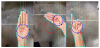
This section labels the fingertips according to convex points pconvex(n) collected in previous stage. The recognition of fingertips can be performed by using the relative position of the fingertip to the known finger webs. For instance, the point representing the fingertip which sits in between of the web of index finger and web of middle finger on the hand contour, is certainly the fingertip of the middle finger. The identity of each fingertip can be easily determined once the identity of each finger web is identified. The output of Algorithm 4 is the labelled fingertips ftip(n), n=0,1,2,3,4 where 0 represent thumb, 1 represents index finger, 2 represents middle finger, 3 represents ring finger and 4 represents pinky. The fingers are labelled from thumb to pinky in red, orange, yellow, green and blue respectively as shown in Figure 11.
2.4.5 Hough line features
Lines can be represented by polar coordinate system, r = xcosθ + ysinθ. Any line can be represented in the form (r, θ) where θ ∈ [0,360] and r≥0. The equation of a Hough line can be written as in Equation 2, where given n pairs of points (x, y), rθ represents the perpendicular distance from the line to the origin at a constant θ.
First, an array of (rθ, θ) is created as the accumulator variable. The size of the array is determined by the desired resolution or accuracy. For instance, for angle resolution, θmin = 1°, the size of θ array, θN =180. Then, find the value of r_θ for every pair of (xn, yn) for all values of θ. Then increment the value of the respective (rθ, θ) in accumulator cell by one. At the end, the pair of (rθ, θ) in the accumulator variable which has higher value signifies potential presence of a line. A threshold, pcount is then set to determine how many iterations is required for the pair (rθ, θ) be classified as a line. In this research, the parameters θmin= 1° and pcount = 5 are used.
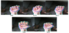
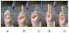
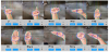
Hough lines detected are used to study the posture of the fingers when fingers are overlapped or when it is hidden inside the palm. In this research, Hough line are extracted from Canny edge detected images as shown in Figure 5(e) and is used specifically for three situations. The first situation is to detect the lines formed by the thumb in fist posture. The mask is for Hough line detection are as shown in the pink circle in Figure 12. The pink circle is slightly vertically higher than the palm circle so that the thumb position will be the center of the mask. It can be observed that both sign ‘E’ and sign ‘S’ both have horizontal Hough line detected as the thumb is above the fingers. Meanwhile, sign ‘T’, ‘N’ and ‘M’ does not have the Hough line detected.
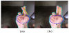
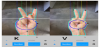
The second situation where Hough line is used is to detect the crossing of fingers by finding the angles of lines of index fingers and middle fingers to differentiate between sign ‘U’ and ‘R’. Sign ‘R’ is the only sign in the scope of this research which involves the fingers crossing with each other. Signs ‘R’ and ‘U’ share similarity in convexity defects and K-curvature properties. Hence, additional features will be required to differentiate these two signs. The crossing of fingers can be detected by finding the Hough lines of the fingers and calculate the angle of deviation of the line representing the fingers. Sign ‘R’ will have Hough lines which are slanted due to finger being crossed as shown in Figure 13, this feature can be used to distinguish the two signs apart.
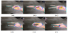
In the third situation, Hough line is used is to identify the roll orientation of hand by detecting presence of fingers inside the palm area when hand is in horizontal orientation. When hand is in default horizontal orientation, fingers are present inside the palm area. When hand is in roll horizontal orientation, there will be no fingers present inside the palm area. This is used to help categorize ‘C’, ‘O’, and ‘Q’ apart from ‘G’, ‘H’, and ‘P’, where the former has no fingers present inside the palm area. However, there is an exception to the case where Sign ‘O’ has Hough line detected despite it is in roll orientation as in Figure 14(b). The size of the square mask is defined by masksqr(x1, y1, x2, y2), and size of mask for circular mask is defined by maskcir(x1, y1, x2, y2). In Algorithm 5, the size of circular and square masks used are determined by defining the area where Hough lines information is required. The Hough lines detected are stored in lHough(n). The angle of the lines in lHough(n), alHough(n) are then calculated.
2.4.6 Identifying posture for fingers
Each individual finger can have three different posture, namely raised, half-raised, and not raised. When two fingers are involved, the variation of position can be extended to fingers crossed or fingers side-by-side. Hence, for each finger, the posture can be quantized into five postures. With the furthest fingertip distance from palm center being a raised finger, second being the half-raised and not raised being the nearest to palm center. After the position of all four fingers webs are identified, the position is utilized to determine which finger do the fingertip detected belong to. This is performed by using the edge of the hand gesture detected.
The edges of hand gestures are a closed contour, hence all neighboring points on the contour can be traced. The status of each individual finger is determined based on the following rule:
- The convex points detected are matched with the respective finger based on the relative position of the convex point on the hand contour to the known finger webs.
- The status of each finger either raised, half-raised or not raised is identified by the distance of the fingertip from the palm center.
- The horizontal distance between two fingers, if it is lower than a threshold, then it is in side-by-side position.
- When criteria 3 is met, check for the edges of the fingers, if the edges are not parallel, then the fingers are in crossed posture.
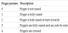
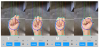
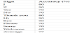
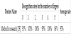
This section labels each fingertip ftip(n), n=0,1,2,3,4 where 0 represent thumb, 1 represents index finger, 2 represents middle finger, 3 represents ring finger and 4 represents pinky. The finger posture for vertical orientation have several shapes which are quantized into five possible state as shown in Table 2. Figure 15 depicts five different quantized level of fingers. Thumb and pinky are exception and only have two postures namely finger posture 0 and 1, which are not raised and fully raised respectively due to the shorter length and location of the fingers on the hand. Table 3 shows the distance criteria used to identify the posture of each finger.
The posture of the finger can be identified by the distance between fingertip and palm center, dtc. Hence, the distance dtc is quantized into three levels. The thumb and pinky are shorter of all fingers and are only quantized into two levels. The distance of quantized level can be seen in Figure 16, where the orange circle represents kraised, while the green circle represents kbent, kth-raised, and kpi-raised.
The posture 3 applies to all fingers other than thumb. The fingers can only be categorized as touching adjacent fingers only when it is fully raised, i.e. fpost= 1. Next, when fingers are side-by-side, the defects are further away from the palm center, as shown in Figure 17. Using these two information, the adjacent fingers can be recognized by applying distance threshold of the defects away from the palm center. For instance, the sign ‘V’ and ‘U’, as well as ‘4’ and ‘B’, both sign ‘V’ and sign ‘4’ have fingers fully raised but not touching each other, hence the defects point between index and middle finger will be further away from palm center.
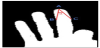
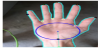
Sign ‘K’ has similar finger posture as sign ‘V’ but the former has the thumb raised in between of index and middle finger as shown in Figure 18. The presence of thumb can be identified by detecting the presence of maximum points, pmaxima(n) in the region between index, middle finger and palm center. If maximum point is detected within the region, it is sign ‘K’, else it is sign ‘V’.
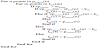
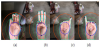
In ASL, there are several signs which involves no fingers being raised explicitly, namely ‘M’, ‘N’, ‘S’ and ‘T’. The identification of these signs involves detection of detailed features which have lesser margin of differences. Convexity defect methods are unable to detect the contours of finger joints as the defect depth are too low. K-curvature method can be used to detect the curves formed by finger joints. This section finds the maximum points which represent the finger joints and the raised thumb, and then identify the position of thumb. First a distance threshold which can clearly separates the thumb from the finger joints is to be set, which is kth-fist. Maximum points which are lower than kth-fist will be classified as middle phalanx, while points higher will be classified as thumb. The feature will be used to classify sign ‘T’, ‘N’, and ‘M’ which has fingers raised and result is as displayed in Figure 19. The position of thumb, kth-post for sign ‘T’ is kth-post= 1; for sign ‘N’ is kth-post= 2; and for sign ‘M’ is kth-post= 3.
2.4.7 Finding hand orientation
There are three axes of orientations of the hand, namely yaw, pitch and roll. Pitch and roll angle will result in partial occlusion of fingers. Hence the usage of 3D depth data or a second camera is required to obtain the accurate pitch and roll angle information. In this research, only the yaw angle and roll angle is taken into consideration. The hand orientation is categorized into vertical orientation as shown in Figure 20 and horizontal orientation as shown in Figure 21 based on the hand yaw angle. The hand orientation is categorized as vertical orientation or in upright position when angle of yaw deviation, ayaw < 60°. The flag is_vertical is then set to true which will be used in Decision Tree classification in the later stage. The hand is categorized into horizontal orientation when the angle of rotation is 60° < ayaw <90°. In this research, the only signs which are in horizontal orientation are the sign ‘C’, ‘G’, ‘H’, ‘O’ and ‘Q’. When ayaw <60°, the signs are in vertical orientation and therefore, ayaw information is used to offset the orientation, and only the signs other than the aforementioned five signs will be considered as candidate signs. Meanwhile the roll angle deviation only takes two possibilities, which is when hand palm is facing directly at the camera or when hand palm direction is parallel to the camera. The roll orientation of hand is determined by using Hough line detection as discussed in Section 3.7.2.7. The flag is_roll is set to true when the hand is facing the side instead of facing the camera, as shown in Figure 22.


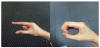
The yaw orientation, ayaw is obtained by finding the angle between palm center and wrist point. Finding point representing the wrist requires utilization of defect points and arm middle line. The arm middle line can be found by first identifying the leftmost and rightmost points on the bottom border. These points are then used to find the middle point of the arm on the bottom border of image. The line connecting this point to the palm center is the line signifying the angle of arm as shown in Figure 23. The wrist point can then be identified by finding the perpendicular intersection point of the last defect points to the line signifying the angle of arm. Lastly, the angle of yaw orientation, ayaw can be determined. The orientation of the hand is set to be horizontal position instead of the default vertical orientation when ayaw >60°.
2.4.7.1 Finding hand motion trajectory
The trajectory motion information of dynamic gesture is extracted using Chain code method. The trajectory motion of hand gesture is quantized into 12 directions, with 30° in each angle, as shown in Figure 24 below. A trajectory information can only be extracted when there are two frames and above. Hence, the trajectory information is only extracted starting the second frame, z >1. In this research, the frames are considered to consist of trajectory motion only when the x or y position displacement of subsequent frames exceeded a certain threshold, in this paper is 10 pixels.
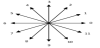
The motion information is obtained by calculating the difference between palm centers in subsequent frames. This can be used to determine the directions in angle of the subsequent movement as well as the speed of travel. The chain code, ccode(n) is then identified. The chain code obtained is then filtered by removing the duplicated codes to simplify the classification process, sccode(m), and the result are as shown in Figure 25.
2.4.7.2 Finding classifying the sign languages
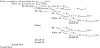
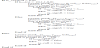
Decision Tree consists of split nodes, which are the internal nodes used to test the input; and leaf nodes, which are the terminal nodes used to infer a set of posterior probabilities for the input, based on statistics collected from training data. Each split node sends the incoming input to one of its children, according to the test result. The proposed framework is able to obtain the posture, orientation as well as the trajectory motion information of the ASL performed in binary representation. Hence the features extracted can be easily classified using simple Decision Tree instead of classification method which requires training. The respective static ASL are able to be classified by identifying the posture and orientation of each individual fingers as shown in Table 4. The dynamic ASL are classified using additional motion trajectory information as shown in Table 5. Simple decision tree can be used to classify the ASL using the following hierarchy:
- Is static or dynamic? Determined by finding the position of hand moment center of all four subsequent frames. If the hand center differs by less than a threshold, it is static.
-
Orientation of hand is vertical or horizontal?
Determined by the palm center to wrist angle, is horizontal if ayaw >60° - Shape representation of finger posture. Determined by calculating the convexity defects, K-curvature and Hough lines.
- Chain code for dynamic gestures. The trajectory motion of gestures are recognized after every four frames. The chain code divides the possible movement of the subsequent frame into 12 sections with 30° each.
3. Results and Discussion
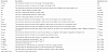
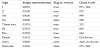
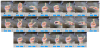
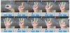
The size of still images sampled are 3264×2448 pixels, while the size of video frames are 720×540 pixels at 30 frames per second. The proposed framework recognizes 29 unique static posture and 10 unique dynamic signs. As some signs are represented by the same static hand posture, the system can translate a total of 44 ASL including 26 alphabets, 10 numerals and 8 ASL words. The alphabetic ASL recognized are as in Figure 26, numeral ASL recognized are as in Figure 27 and lastly dynamic ASL are in Figure 28 below.
The experiment is carried out separately for static ASL and dynamic ASL. For static ASL, 50 images are collected from 5 different signers for each of the 29 static ASL. A total of 1450 images of static ASL are collected. For dynamic ASL, 10 videos are collected from each of the 10 dynamic ASL, which consist of a total of 100 videos. The proposed framework uses calibration of hand threshold instead of training of classification database, hence all images can be used as test images. The recognition rate for the experimental results obtained for static ASL are as shown in Table 6.
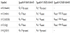
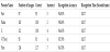
The recognition rate for experimental results obtained for dynamic ASL are as shown in Table 7. For some test images, the features extracted do not match any of the predefined rules of the ASL groups. For these images which could not be recognized, they are not classified into any classes of sign language, hence some test images will not be have classification result. Based on the proposed framework, the average accuracy achieved for 29 static ASL is 85.72%, and average accuracy achieved for 10 dynamic ASL is 77%.
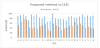
In this research, the experimental results of two other sign language recognition work is carried out to verify the performance of the proposed method as compared to the benchmark researches. First, a state-of-the-art appearance-based sign language recognition framework experiment based on SURF and SVM are carried out. The experiment is based on research [13] which extracts SURF features from the hand gestures. The SURF features extracted are clustered into 29 classes using K-means clustering method. Next, BoF is applied to represent the SURF features with probability features in order to to simplify the dimensionality. Lastly, a one-vs-all SVM is then applied classify the test images. Using the dataset collected in this experiment, with 50 test images from each 29 classes, a 10-fold cross validation is performed. The recognition of six classes of gestures obtained by the author in [13] are as shown in Table 8. Whereas the average accuracy obtained using the dataset collected in this experiment, the accuracy of recognizing 29 classes of ASL is 48.48%, as shown in Figure 29. Similar recognition approaches are also used in research [14,15].
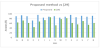
The second benchmark experiment done is a model-based approach. The experiment is based on method in research [29]. In the research, distance transform is used to obtain the palm center and radius information. Convexity defects is then used to extract all the fingertip position. Decision Tree method is used in classification stage. The database used for this experiment is only 15 static ASL, this is because it is not able to recognize horizontal orientated signs namely ‘C’, ‘G’, ‘H’ ‘O’ and ‘Q’ as well as signs in fist posture namely ‘M’, ‘N’. ‘S’ and ‘T’. Also, gesture which are similar such as ‘V’ and ‘U’ are unable to be determined with the limited features. The average accuracy achieved for second experiment is 65.73%. Table 9 shows the accuracy obtained from the recognition of five gestures in research [29]. The accuracy of recognizing 15 ASL using the benchmark method are as shown in Figure 30.
From the research conducted in paper [13], the number of gestures used are only six, and the average accuracy obtained is 96.23%. However, when the number of gestures is increased to 29 gestures instead of six in our experiment, the accuracy greatly deteriorates to 48.48%. It is because as the number of classes increases, the separability between the SURF features of different gestures decreases, hence, the misclassification rate increases. Furthermore, in appearancebased recognition framework, expensive feature extraction and computational time are required to extract and to train all the visual features from the images, which are also stated in research [23].
In 2D model-based approach, convexity defects are a notable method for fingertip recognition. In order to demonstrate the effect of selection of features in affecting the scalability of the gesture, the second experiment is done using method as described in [29]. The feature extraction phase is replaced using the method in [29] while all the other stages uses the same as the proposed method as only the feature extraction algorithm are to be compared. However, only 15 ASL are able to be recognized, as there are not enough features and rules to define the other ASL. The average recognition rate achieved is 65.73%. This first experiment shows that model-based convexity defects can perform better than the commonly used appearancebased method such as the SURF and SVM techniques. The use of convexity defects and its intrinsic nature of describing the fingers are proven to outperform the SURF and SVM appearance-based feature extraction methods. The second experiment shows that the proposed convexity defect method out-performed the method used in [29] due to a more well-defined set of features and rules. The similar convexity defect rules are also observed in research [19,25,30].
In this paper, the classification criteria of each ASL are written explicitly, and as opposed to appearance-based method, it does not require computational heavy algorithm. The classification of ASL can be achieved by implementing a low computational cost Decision Tree classifier. The average accuracies achieved is in our paper is 85.72% for
29 static ASL and 77% for 10 dynamic ASL. The use of finger webs as an intermediate feature in determining the fingertips is proposed in this paper. The finger web has the advantage of being always present despite different posture of hand gestures. This allows the potential fingertips candidate from convexity defects and K-curvature features to be correctly identified to each finger of the hand despite various hand posture. The usage of Hough line feature in finding the edges of the fingers allow ASL which are visually similar to be differentiated. Besides, algorithm designed to specifically differentiate two different visually similar ASL has shown to be able to differentiate the ASL apart.
With robust rules and features being implemented based on convexity defects, K-curvature and Hough line, the framework can be extended to recognize different posture of hand gestures. This includes other Sign Languages and also different varieties of hand gestures. The recognition of new signs can be achieved by defining the finger representation and other features representing the new signs, and these features can be appended to the signs already defined in Table 4. Decision Tree classification can then be used to classify the new signs when the feature criteria of the new signs added is met.
The proposed method uses the 11 scale-invariant k parameters introduced in Table 1. The coefficients in the parameters are the measurement of the ratio of different hand landmarks with respect to the palm circle. This allows the framework to be scale-invariant and hence is also adaptive to different sizes of hand.
The coefficients are optimally obtained through measurement of ratio that best represents the hand anatomy of signers. The coefficients can be represented by lines and circles as shown in Figure 3 and Figure 4 respectively. The accuracy of the algorithm does not rely directly on the values of the coefficients. Its function is to set a rough estimation or reference on the location of each hand landmark. For instance, the finger web of the thumb should fall between the vertical lines representing kth and kin. They can be verified visually and can be easily recalibrated if required. The optimum coefficients are then tested and verified through different hand posture of 5 different signers.
The same set of coefficients has been shown to be able to recognize ASL by five different signers with different palm size. It can be extended to recognize other signers with similar hand anatomy. When ASL of new signers with relatively different hand ratio such as a larger palm with shorter fingers are introduced, the framework has the flexibility of calibration of the coefficients to recognize ASLs of new signers. As with other sign language algorithms, when outliers are introduced to the system, calibration or training of classifiers will be required to obtain better accuracy.
In this research, the experiment is performed in indoor locations, all under well-lit lighting conditions. The segmentation accuracy might be affected when subjected to a different or extreme background lighting condition. The proposed feature extraction framework is however independent of the segmentation techniques used in this research. Hence, the framework can be implemented with other segmentation methods that can output two information of hand gestures, namely edges information as shown in Figure 5(e) and binary information as in shown Figure 5(g). Thus, different segmentation methods can be used to improve the segmentation accuracy of the proposed framework in real-world applications such as with different skin color or background conditions.
This research is implemented on a smartphone to facilitate the image data collection process and can be implemented on other platforms and devices. Lastly, this paper proposes a sign language recognition framework with the aims to contribute to the bridging of communication gap between the deaf and the rest of the society.
4. Conclusion
In appearance-based recognition framework, expensive feature extraction and computational time are required to extract and to train all the visual features from the images, which are also stated in research [23]. This is not required in the proposed method. In 2D model-based approach, convexity defects is a notable method for fingertip recognition as its intrinsic nature of describing the fingers are suitable to be used to describe the fingers’ posture. In this paper, the classification criteria of each ASL are written explicitly, and as opposed to appearance-based method, it does not require computational heavy algorithm. The classification of ASL can be achieved by implementing a low computational cost Decision Tree classifier. The average accuracies achieved is in our paper is 85.72% for 29 static ASL and 77% for 10 dynamic ASL. The use of finger webs as an intermediate feature in determining the fingertips is proposed in this paper. The finger web has the advantage of being always present despite different posture of hand gestures. This allows the potential fingertips candidate from convexity defects and K-curvature features to be correctly identified to each finger of the hand despite various hand posture. The usage of Hough line feature in finding the edges of the fingers allow visually similar ASL to be differentiated. Besides, algorithm designed to specifically differentiate two different visually similar ASL has shown to be able to differentiate the ASL apart. With robust rules and features being implemented, the framework can be extended to recognize hand gestures with different posture including other Sign Languages. The recognition of new signs can be achieved by defining the finger representation and other features representing the new signs, and these features can be appended to the system. Decision Tree classification can then be used to classify the new signs when the feature criteria of the new signs added is met. Lastly, this paper proposes a sign language recognition framework with the aims to contribute to the bridging of communication gap between the deaf and the rest of the society.
Competing Interests
The authors declare that they have no competing interests.