


1. Introduction
Most nowadays systems are software-intensive, i.e. systems for which software is a major technical challenge and is perhaps the major factor that affects system schedule, cost, and risk [1]. As systems become more complex and distributed, the challenge of architectural design is increasing, since it requires the consolidation of many requirements and attributes. There are many definitions for the term software architecture, but all of them agree that the architecture is the heart of every system, determining its structural and behavioral principles, directing and constraining following design and implementation stages. It is also well perceived that architectural changes to a system, in later development stages, are the most difficult. Therefore, software architectural design is critical to the entire system's life-cycle.
A software architecture is designed on the basis of requirement specifications, which are supposed to define the capabilities and properties that the system should possess, both functional and non-functional. Requirement specifications, however, tend to focus mainly on the system functionality, whereas quality attributes are, in many cases, expressed in general terms, and sometimes even being overlooked. Moreover, it is a common practice to define the set of functional requirements as dynamic scenarios, e.g. use cases or user stories, whereas its quality attributes (the non-functional requirements) are defined in static terms, requiring the system to be safe, secure, available, etc. On the other hand, the impact of quality attributes on the architecture is much greater than the functional requirements. For example, all the cars in the world have the same functionality: carrying a group of people from one location to another. Cars, however, differ by the way they are architected, e.g. the engine technology (fuel, electricity or hybrid), the transmission (manual or automatic), the materials (metal, plastics, etc.), the internal space, comfort, aerodynamic design and more. These are selected according to the quality attributes expected from the car, such as performance, safety, usability, availability, cost of operation, etc. Considering quality attributes during the architectural design process and incorporating them into the architecture can improve significantly the quality of the constructed architecture and to increase stakeholders' satisfaction.
In this paper, we introduce a two-phase systematic approach to software-intensive architecture design, which incorporates both functional requirements and quality attributes (i.e. non-functional requirements) into a functional architecture which satisfies both. In the first stage we show how to systematically derive all the views of an initial functional architecture from the defined functional scenarios. In the second phase we revisit the functional scenarios, but now as "Devil's Advocates"1, investigating cases where the functional scenario may fail according to an undesired event. These events are directly related to the violation of quality attributes, such as performance, availability, security, safety, etc.
1In common parlance, the term devil's advocate describes someone who, given a certain point of view, takes a position he or she does not necessarily agree with (or simply an alternative position from the accepted norm), for the sake of debate or to explore the thought further [Wikipedia].
Our approach is based upon the fact that run-time quality attributes (i.e. those who may be violated during system operation) occur only while it is active performing its tasks. More specifically, while the system is running, something happens (e.g. a server crashes or an intruder is identified), which might cause the system to fail (i.e. not being able to accomplish its task as required). Therefore, such an event causes deviation from the normal functional scenario. The role of software/system architects is to propose both structural and behavioral solutions by which such events may be identified and reacted-upon, in order to prohibit the fault (the undesired event) from causing a failure (of the entire task). When the system's functionality is challenged by possible faults, the designers have to react by designing an appropriate reaction, which will attempt to get the system back on tracks. The proposed reactions yield two results: (1) new quality scenarios, which describe the reaction (i.e. how should the system behave in such cases), and (2) modifications to the structural architecture needed to support the newly-derived functionality.
In order to explain better and demonstrate our architectural design process, we are introducing a case study of a Car Navigation System, using UML (the Unified Modeling Language)2 as the modeling language for the various views of the architecture. We assume that the reader is generally familiar with UML, and therefore provided only brief explanations about the features of the language, when applicable. The UML diagrams in the various figures have been edited using the Enterprise Architect software tool (by Sparx Systems3), version 12.1.
2. The Car Navigation System Case Study
Before we start the introduction and discussion of our proposed approach and process, we would like to introduce a case study of a typical popular Car Navigation System (abbreviated CNS).
A CNS is a computerized assistance tool which enables the driver to navigate along a chosen route from one location to another. A typical business in which such a system might be installed is a driver with a car, who usually uses it to apply three main business scenarios:
Planning a trip: determining an origin location and a destination location and setting up priorities and constrains (e.g. only toll-free routes);
Navigating along a route: displaying dynamically the route and the car location on the relevant map section and continuously checking the relation between the actual and the expected location of the car. When a significant deviation is indicated, an alternative route is proposed;
Launching a traffic report: creating and reporting an event, an obstacle or any other entity (e.g. police), by the driver. Such reports may be distributed to other relevant drivers.
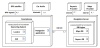
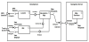
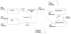
Not long ago a CNS was a stand-alone instrument, installed in a car, containing a local map database and satellite communication, which enabled to apply only the first two business process. As cellular internet communication developed, typical CNSs turned into a Smartphone application, which uses the GPS-based location capabilities of the phone, to locate itself, and external servers who provide geographical and traffic data, as well as other services (e.g. route calculation, advertisement, social communication etc.). Therefore, a popular physical architecture of a CNS is structured as depicted (by a UML Deployment Diagram) in Figure 1. 3-dimentional boxes represent physical (hardware) nodes and execution environments within them, whereas rounded squares with a 'document' icon represent software artifacts installed within the nodes. The lines between nodes represent physical links, labeled by their type. The multiplicity (a label of the form min..max) represent the minimum and maximum instances of the related entity that must be present in any configuration of the architecture, where * denotes 'many' (i.e. any integer > 1). Note that a minimum multiplicity of 0 means that, that node is only optional (these nodes are shown in white color for clearance).
2http://www.uml.org
3http://www.sparaxsystems.com
Usually, an architecture has to be derived from the business needs and is expected to support them. However, since the smartphonebased client-server architecture is a popular platform, it may be considered as generic to many applications. Therefore, we are assuming here that this physical architecture, along with the business processes, are the prerequisites for our architectural designed process, which will be detailed in the following.
3. Functional and Non-functional Requirements
3.1 Types of requirements
System/software requirements are usually divided into two types, as defined in [2]:
Functional requirements, which are statements of services the system should provide, how the system should react to particular inputs, and how the system should behave in particular situations;
Non-functional requirements, which are constraints on the services or functions offered by the system such as timing constraints, constraints on the development process, standards, etc.
Both types of requirements affect the design of a system, but they are usually treated differently. Within the software solution domain, for example, functional requirements are usually implemented by functions and interactions (i.e. function calls and responses, message transfers etc.) within the software application, or between the application and its external environment. Moreover, each functionality may usually be spotted at a certain location in the code. Non-functional requirements, however, are sometimes satisfied by selecting different implementation of the functions. For example, a requirement to construct a sorted list from an unsorted one may be implemented by various sort algorithms, with different complexity - depending on the required time/space performance constrains.
Non-functional requirements, on the other hand, are often applied to the system as a whole rather than individual features or services [2]. For example, the response time of a system to a request may depend on various characteristics of various software components, e.g. the algorithm, the communication protocol, the structure of the data, the degree of concurrency, and more.
In many other cases, however, non-functional requirements are satisfied by applying certain functionality which is expected to provide the desired resolution. For example, security may be implemented by encryption, authorization or authentication mechanisms, availability may be implemented by ping/echo and re-routing mechanisms, accuracy performance may be implemented by approximation and compensation algorithms, and so forth. This approach, of turning non-functional requirements into corresponding functional requirements, lies in the heart of the process proposed in this paper.
3.2 Non-functional requirements are often Unspoken
In order to design and build a satisfactory system, explicit requirements are needed. Such requirements are not only the basis for the system design and implementation but are also the basis for its verification: Acceptance tests are usually based upon a set of system requirements which, when satisfied, define a threshold for the acceptable quality of the system by its client and other stakeholders. We evident, however, that some characteristics of the system are not always explicitly communicated by the client or other stakeholders, although they still exist at their unconscious expectations. Such expectations might be revealed only after delivery, in validation tests or in field operation. For example, A user might not explicitly require an "undo" function, but the first time he or she wants to recover from a mistake they will notice the absence of such capability. Such implicit or expected requirements are usually called unspoken (or tacit) requirements (as described in [3], based upon the "Kano Model" [4]). Unspoken requirements have two effects:
- They turn down the satisfaction level of the stakeholders, since the stakeholders consider such features as "must-be quality" [4], i.e. the system developer should have expected that such a feature will be needed and should have implemented it, even if it was not explicitly specified;
- Adding such a feature to the system in late stages of development, or even after delivered, might be difficult.
The second effect might have significant implications when the changes needed to support the missing characteristics are in the underlying architecture. Nevertheless, requirement specifications usually concentrate on system functionality, while non-functional requirements often remain unspoken or vague. The "undo" example falls under the category of system usability - the quality attribute that makes the system better usable for the user. In many cases this is expected to be covered by a vague non-functional requirement such as "the system should be user friendly".
Unfortunately, non-functional requirements affect the entire system (as mentioned above) and therefore its underlying architecture, which is usually designed at early development stages, and is difficult to be changed at later stages. Consider, for example, the case where a client, who already owns a system, requires to just one feature – that the system should continuously operate 7 days a week, 24 hours a day. The immediate solution of duplicating the resources may require further architectural changes to support data integrity, backup, resource selection, handoff, etc.
The architectural design process described further in the paper directly addresses this effect.
4. Functional Scenarios and Functional Specificaton
4.1 Functional Scenarios
The ISO/IEC/IEEE 12207 standard [5] defines the architecture of a system as fundamental concepts or properties of a system in its environment embodied in its elements, relationships, and in the principles of its design and evolution. Although a software-intensive system architecture is often perceived as a system structure, it cannot be properly designed without referring to its behavior: Many structural attributes are derived from the way the system operates, such as which components need to interact (with each other or with the external environment), what should be the communication bandwidth, which functions should be allocated to which system components, etc. Philippe Kruchten, in his memorable 1995 paper entitled Architectural Blueprints- The “4+1” View Model of Software Architecture [6] initiated and inspired the approach that operational scenarios (use-case view) should be at the center of the software architecture, impacting all its other views.
Although the operational capabilities of a system are captured in its functions, the entire functionality of a system is described by its functional scenarios. Therefore, while a system possesses certain functions, these functions may be applied in different orders in order to perform different functional scenarios. For example, an ATM (Automated Teller Machine) may be capable of performing the following functions: (a) approve access to a user (b) dispense cash (c) interact through touch-screen (d) print a slip (e) check user's balance. However, a cash withdrawal scenario is performed by applying the (a)→(c)→(e)→(b) sequence of functions, whereas a balance printout scenario is performed by applying a different sequence, namely (a)→(e)→(d). Moreover, while every function yields a specific result, the results (goals) achieved by the first scenario are obviously different from the results achieved by the second one.
In this view we may define a functional scenario as a sequence of function applications executed to achieve one or more goals. The functions are applied throughout possible interaction of the system (e.g. the ATM) with its external environment (e.g. the human user, the bank's database server).
Since software-intensive systems are interactive and dynamic in nature, functional specifications are usually defined in a form of scenarios. One example is the user stories approach, used in agile software development processes, as defined, for example, in [7]: A user story is a very high-level definition of a requirement, containing just enough information so that the developers can produce a reasonable estimate of the effort to implement it. User stories are often written in the form of "As a (role) I want (something) so that (benefit)", as suggested by Mike Cohn [8]. A more detailed form of functional scenarios is use cases, which will be described in detail in the following.
When writing functional scenarios, it is possible to perceive the system as a black box, i.e. without specifying upfront its set of basic capabilities (functions). However, when these scenarios are implemented by the developers it is expected that they know which functions are already available for them, and to reuse these functions; new functions should be added to the system only when there is no function readily available to use. Thus, any functional scenario should be analyzed prior to its implementation to reveal the functions need to implement it. Moreover, since each function is executed at the responsibility of a certain component of the system, implementors should be aware of the system architecture, from which they learn about the "cost" of applying such a function, in terms of communication, computation and storage resources. The process of revealing the required system functionality and relate it to the architecture is described later as the process of functional analysis.
Non-functional requirements, as mentioned above, usually constrain the way the functionality is implemented. At this stage of requirement specification, it is not necessary to get into the implementation details, and therefore the relevant non-functional requirements may be just related to the scenarios, deferring their addressing to the implementation stage. Nevertheless, there are two pitfalls in this decision:
- Some non-functional requirements have architectural impact, which we should be addressed as principle decisions, guiding the detailed implementation. For example, an availability issues may be resolved by using duplicate servers, which backup each other, instead of a single one.
- Some non-functional requirements are tacit (unspoken) and therefore might be overlooked. Revealing them at the final system tests or after deployment may cause costly repair or even re-design. Later in this paper we will show how to reveal those unspoken requirements as early as possible.
- As mentioned above, a more formal way to write functional scenarios is use cases (e.g. [9,10]), which will be described next.
4.2 Use cases diagrams
The entire set of a system's use cases capture its functionality as a set of scenarios, each of which is interpreted as "one case for using the system". Use cases may be specified at various levels, e.g. as business processes at the business level, as system processes at the system level, as internal processes at a subsystem or component level, etc. Although in this paper we will refer to system-level use cases, i.e. the processes performed by the system as a whole during its operation, it should be noted that these system level use cases are derived from the business level ones. The detailed description and discussion of the derivation method is beyond this paper, but as an illustrative example we may look at the business process 'using an elevator' which may be broken down into two system-level processes: 'calling an elevator' and 'travelling by elevator'. Although these two processes comprise the using of an elevator, for the purpose of getting from one floor to another, they are independent upon each other, since a user may call an elevator without travelling, or travel by an elevator without calling it (e.g. by joining an already-travelling elevator).
The set of use cases of a certain system may be reflected in two views:
- The global view, which shows the relation between the set of use cases (implemented within the system itself) and the set of external entities (called actors), with which the system interacts during its operation;
- The individual view, which addresses each use case separately by a detailed use case specification.
The two views are dependent upon each other, since the behavior of any single use case may affect the entire set, and vice versa. Therefore, it is always a debate which view should be generated first. For the brevity of the following we start with the global view, by using the commonly-used model of UML Use Case Diagram.
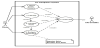
Figure 2 describes the system-level use case diagram, which depicts the global view of the entire set of system use cases. It should be noted that the main three aforementioned business-level scenarios, namely 'Planning a Trip', 'Navigating along Route' and 'Sending a Report' are replaced here by corresponding system-level use cases, complemented with other uses cases related to them by << include >> and << extend >> dependencies (labeled dashed arrows). The formal meaning of these dependencies is not discussed here, but informally they may be interpreted as follows:
- A << include >> B, if use case B is always executed during the execution of A, at a specified inclusion point;
- B << extend >> A, if use case B is optionally executed during the execution of A, subject to the occurrence of an event or condition at a specified extension point.
The squared frame (bearing the title of the system) denotes the system boundary, i.e. the border between the internals of the system (use cases, denoted as ellipses) and its external entities (actors, denoted as stick-figures). When an actor is connected by a line to a use case it denotes that that actor interacts with this use case. When the line is arrowed, it denotes that that actor may initiate the use case. In this example we chose, for brevity, a system configuration (see Figure 1 ) in which the optional nodes (i.e. the radio audio and the maps and reports providers) are not present. Therefore, the Driver is the initiator of the main use cases whereas the GPS Satellite is a supporting actor for the Locate Self use case (which appear to be included in all other use cases). Also note that the Calculate Route use case is included in Plan Trip, since it is always performed there, but it extends Navigate along Route, since it is invoked only at the event of deviation from the route.
4.3 Use case specifications
- Any use case has a use case specification which includes the following elements:
- Actors. An actor is any entity, external to the system, which directly interacts with the system. There are two types of actors:
- A primary (an initiating) actor - which initiates one or more use cases, in order to achieve a goal; Not every use case needs to have primary actors – a use case is sometimes initiated according to an internal event or condition within the system. For example, an internal BIT (Built-in-Test) is automatically performed periodically, without any external trigger. A use case without primary actor may be called spontaneous.
- A supporting actor - which is initiated during one or more use cases upon system's request. A supporting actor has no specific goal to be achieved through this interaction, rather than assisting the system in achieving the primary actor's goal.
- Other Stakeholders. A stakeholder (of a specific use case) is any entity who may affect the execution of the use case or may be affected by it. Actors, naturally, are stakeholders, since their interaction with the system affect the execution of the use case and they benefit from it. Other stakeholders are those who do not interact with the system during a use case, but they have certain interests in the execution or in the results of the use case. A typical example is a safety regulator that requires that the system will preserve the health of its user during the execution of a use case. A more specific example is the bank owners, who require that an ATM will collect a fee while performing a withdrawal use case initiated by a user.
It should be noted that stakeholders, who are not actors, have no graphical representation in UML's use case diagram. The architect must, therefore, take care of their definition in another way.
- Preconditions. Preconditions are logical assertions that must be satisfied in order for the use case to be able to execute. Preconditions are not checked as part of the use case, but without their existence the use case might not have meaning. For example, a user cannot execute a travel in an elevator if an open elevator is not available at her current floor. The precondition 'an open elevator is available at the floor' may be satisfied either by calling an elevator, prior to traveling, or when an elevator stopped at the floor as a result of another user's 'travel' use case.
- Post-conditions. Post conditions are logical assertions which must be satisfied upon the completion of a use case, in order to define its "success". A use case is considered successful when (a) the primary actor's goal has been achieved and (b) when all the interests of the other stakeholders has been fulfilled. For example, a withdrawal use case of an ATM is successful only when the user (the primary actor) possesses the amount of money requested, and her account shows a debit for that amount + withdrawal fee, for the interest of the bank owners.
Note that a use case is considered successful only from the actors' and stakeholders' viewpoint, and not from the system's viewpoint; the system must perform successfully in both "successful" and "unsuccessful" (or "failure") results. For example, the system should successfully fail a withdrawal use case when the user's balance is insufficient.
- Trigger. Trigger is the event that initiates the use case. The trigger is caused by either a primary actor or by the system itself (when the use case is spontaneous). In many cases the trigger may be caused subject to given pre-conditions; in such a case the meaning is that the trigger event cannot occur at all. For example, submitting a registration form to a site can be performed only if the "submit" button is displayed and enabled.
- Main Success Scenario (MSS). The main success scenario is the shortest and most straightforward way to go from the trigger to the successful completion of the use case (i.e. when all the primary user's goals have been achieved and all the other stakeholders' interests have been fulfilled).
The MSS (as all other scenarios in the following) is a single-track numbered sequence of steps describing the interactions between the system and the use case's actors (both primary and supporting). Each of these steps describes a single action performed either by an actor or by the system. Naturally, the first step describes the reaction of the system to the trigger. As described above, each step involves either the application of one or more of the system's functions (when the step is performed by the system) or an input/output function (when the step is performed by an actor).
The steps of the MSS are describes in a "success-oriented" fashion, i.e. they are deterministic and express only the positive conditions, under which the scenario may proceed successfully. For example, after the user entered her PIN to the ATM, the system's step should not be 'the system checks the PIN' but rather 'the system approves the PIN'. The first one is nondeterministic and causes the MSS to split into a two-track sequence, whereas the second one, if succeeds, enables the MSS to continue in its single-track sequence. If the step fails (e.g. the PIN was not approved) the MSS is discontinued. If there is a branch (see next) that specifies the case when this failure condition occurs, it will continue the scenario.
- Branches. Branches are deviations from the MSS (or from other branches) which may be caused when the original scenario cannot perform a certain step. Each branch should specify its entry condition in terms of location (i.e. in which step of the original scenario) and condition (i.e. what happened in the original scenario). Regarding the previous example, a branch specifying the sequence of actions to be performed when the PIN in not approved, will be forwarded by a sentence of the form 'in step N of the MSS – the PIN was not approved'.
Branches are scenarios of their own, i.e. they are also specified as sequences of interactive steps. Their numbering may me derived from the original sequence. E.g. steps numbered 6A1, 6A2, etc, specify the set of the steps of branch A, deviated from step 6 of the MSS, whereas steps numbered 6A3B1, 6A3B2, etc, specify the set of the steps of Branch B, deviated from step 6A3 of Branch A.
Branches may be categorized into two types:
- Alternative - a branch whose sequence of steps would lead to "success" (i.e. all post-conditions satisfied);
- Exception - a branch whose sequence of steps would lead to "failure" (i.e. not all post-conditions satisfied).
This categorization plays a crucial role in the quality scenarios, which will be described in the following.
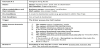
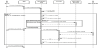
Figure 3 below Describes the "Navigate along Route" use case which appears in the use case diagram of Figure 2 (the underscored text is explained later).
5. Functional Analysis and Functional Architecture
5.1 Functional Analysis
As mentioned above, from the system’s point of view, a functional scenario is a sequence of function applications. Since these functions should be implemented by functional components (e.g. software modules), we first need to identify the required functions, reflected in the functional scenarios, and check whether this function is contained within the existing architecture. If not, the function should be allocated to a component or propose a change in the existing architecture by introducing a new functional component and integrate it into the architecture. If no architecture exists yet, an initial one may built, by proposing a set of initial functional components, collecting all the required functions from all the use cases, and allocating them to these components.
Functional Analysis is the process described above, and is defined in ISO/IEC/IEEE 24765:2010 [11] as follows:
"Examination of a defined function to identify all the subfunctions necessary to accomplish that function, to identify functional relationships and interfaces (internal and external) and capture these in a functional architecture, to flow down upper-level performance requirements and to assign these requirements to lower-level subfunctions"
We have highlighted some of the terms, in order to interpret them in view of our use-case-based approach, as follows:
- Defined functions are the use cases themselves: each use case is actually a service (high-level defined function) of the system;
- Subfunctions are the functions that the system should apply while executing a use case. These can be identified in the trigger(s) and in all the steps of both the MSS and all the branches of the use case. In the use case specification in Figure 3 the subfunctions, which should be implemented in the system, are marked with a single underscore, whereas the user inputs, to which the system have to respond, are marked with a double underscore. Once identified, these functions need to be assigned to functional components;
- Functional relationships and interfaces comprise the structural view of the functional architecture, which is constructed from a set of chosen functional components, to which the subfunctions are assigned. Functional architecture is explained in Subsection below.
- Upper-level performance requirements refer to the nonfunctional (quality) requirements, which are expected from the use case, and their assignment to the lower level subfunctions is the concern of following Sections.
5.2 Functional Architecture
A functional architecture is the set of functional components, their assigned functions and their internal and external interface. The entire architecture of a software-intensive system may be reflected in four views [12]:
- The physical structure view: The physical (hardware) components and their physical communication links. This view may be modelled as a UML Deployment Diagram, as shown, for example, in Figure 1;
- The functional structure view: The set of functional components, identified in the interaction view with their internal and external interfaces. This view may be modelled as a UML Component Diagram, as will be shown below;
- The combined structure view: The allocation of functional components to physical components and the mapping between functional and physical interfaces. This view may be modelled as a UML Composite Diagram.
- The interaction view: The implementation of the use cases as interactions among a set of functional components, either with each other or with the external environment. This view may be modelled as a set of UML sequence diagrams;
The term functional architecture discussed here refers mainly to the functional structure view.
It is directly implied that the interaction view and the functional structure view are tightly coupled, since they both refer to the same set of functional components. Furthermore, according to the functional analysis process described above, this interrelationship has the "chicken and egg" effect: functions are to be assigned to functional components and functional components are built in order to implement function. When a system is initially built "from scratch" it can start with an initial selection of functional components, constructed by grouping all the subfunctions identified in the use cases into (highly cohesive) function groups - each of which defines an initial functional component. The implementation of the upper-level functions (i.e. the use cases) is then may be designed, comprising the interaction view. The interfaces among the functional components, and between functional components and the external environment, is directly derived from the components' interaction needs (i.e. two components need a functional interface if and only if they have to interact with each other).
In this paper we do not explicitly detail the construction of the interaction view; we rather intuitively define a set of functional components, based on the functions identified in the use cases. These components correspond to the software artifacts shown in Figure 1 (except that the two DBs are considered as a single functional component (Map Services). Consider, for example, the set of (underscored) functions in Figure 3, and assume that similar function-identification has been performed over the entire set of use cases of this case-study. The result might be a functional structure view (UML Component Diagram) as shown in Figure 4, and the list of components and their assigned functions from use case #2 are shown in table 1 . When a component requires a service (i.e. call a function) from another component, it uses its appropriate required interface (a short line with a half-circle at its end). When a component enables other components to use its services (respond to a function call) it exposes a provided interface (a short line with a full circle at its end). Interaction between components is performed, therefore, through a pair of required-provided interfaces. "Free" interfaces, which are not paired with others, denote interaction with the external environment.
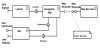
The dashed arrow between the Map Requests pair of interfaces denotes that the specification of the (provided) interface is determined by the Map Services component (which resides on the server side) and the (required) interface on the Navigation App side depends upon it (i.e. needs to be adapted accordingly). The note "static binding" specifies the binding strategy between these pair of components; binding strategies will be elaborated later.
The physical architecture view ( Figure 1) and the functional architecture view ( Figure 4) must be consistent with each other. This is depicted in the combined architecture view ( Figure 5), which shows how the components of the functional architecture are deployed onto the nodes of the physical components. If two components interact within the same node, they may maintain their existing interfaces. However, when the interaction is performed over physical links, the functional interface must be delegated to/from communication ports, which enable the physical communication. Figure 5 below shows the combined architecture view of the CNS in the form of a UML Composite Diagram. Note that the nodes of the physical architecture4 are denoted here as parts (rectangles) equipped with ports (small squares on the parts' circumferences), indicating the ends of physical links. Cross-node and external functional interface are related to corresponding ports with << delegate >> relation.
4The << execution environment >> blocks are not shown, for brevity.
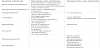
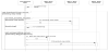
Part of the interaction view, which implements use case #2 as an interaction between the functional components, is shown in Figure 6 as a UML Sequence Diagram. Note that the messages marked 1.xx denote the steps of the trigger+MSS, whereas the messages marked 2. xx denote the steps of Branch A.
Up to this stage we have dealt only with the functional requirements, as reflected in the functional scenarios, i.e. the use cases. Next, we will introduce the quality attributes (non-functional requirements) and show how they might impact the functional architecture.
6. Quality Attributes and Quality Scenarios
6.1 Run-time quality attributes
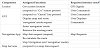
The quality of a system is the degree to which the system satisfies the stated and implied needs of its various stakeholders, and thus provides value. This definition is cited from the ISO 25010:2011 standard [13], which defines a quality model for (software-intensive) systems, enlisting the specific characteristics that should be possessed by a system in order to assure its quality. These characteristics are often referred to as quality attributes. According to this standard there are eight quality attributes, which are further decomposed into more specific sub-attributes, as shown in table 2. However, the impact of these attributes and sub-attributes on a system differs in two significant aspects, which leads to divide them into two categories:
- Those who affect the way the system behaves and responses to various events during its operation;
- Those who affect the (architectural) design of a system, by imposing an architecture which should satisfy them.
We refer here to attributes of the first kind as run-time attributes, whereas the second kind will be denoted here as design-time attributes. Accordingly, we have divided the sub-attributes in table 2 into these categories.
This categorization requires further explanation: Run-time attributes actually define situations that may or may not happen while it is operating. Time behaviour (under performance efficiency), for example, may be maintained during most of the system operation, but also might be violated at peak times. Considering this quality attribute (non-functional requirement) may impose changes in the system behaviour, e.g. how to recognize time-behaviour violation, how to respond to it and how to recover from it. In other words, additional functionality should be incorporated into the system, regarding quality attributes. In the following Sections we suggest how to address this issue. Needless to mention that an inoperable system never faces time behaviour violations.
Design-time attributes are addressed when the system undergoes development stages, either at initial development or during maintenance cycles. Adaptability (under Portability), for example, does not affect the functionality of the system (i.e. what should the system do), but it rather impacts the way this functionality is implemented, in order to enable its adaptation to various environments in the future. In the scope of this paper, we refer only to run-time quality attributes, since, as shown in the following, they have significant effects on the operational scenarios (use cases) of the system.
6.2 Quality Scenarios as use cases
Since quality attributes have significant influence on system behaviour, there is a natural relationship between them and the functional scenarios. Suggestions for such relationships appear in other works, such as [14-16] and more. In this work we take this idea one step further, and incorporate quality scenarios directly into the use cases, to create a single unified functional model. In order to do so, we start with quality scenarios on their own, mapping them later into our use-case specifications.
Bass, Clements and Kazman [17] provided a format for quality attribute scenarios, containing six parts, as follows:
- Stimulus is an event that happens during system operation, indicating violation of a quality attributes. Examples may include loss of communication (violating availability), an attempt to access confidential material (violating security) or memory overflow (violating resource utilization);
- Environment (or context) is the configuration or circumstances under which the stimulus may occur (e.g. in maintenance configuration, when the system is on-line);
- Stimulus source is the entity which initiates the stimulus. This entity may be external to the system (e.g. a user, a remote computer) or the system itself (e.g. by throwing an exception, raising a flag or invoking a watchdog);
- Artifact(s) are the parts of the system (including the system as a whole) affected by the stimulus (e.g. CPU, disk, communication channel);
- Response describes the course of actions the system performs when a stimulus occurs. Part of the response should be the indication that a response happens (e.g. catching the thrown exception, checking the status of a flag). The following steps may include various action, such as disabling the stimulus source, repairing the damage, if incurred, or recovering and getting back to normal operation;
- Response measure is the means by which it can be decided whether the response was satisfactory (e.g. how long did it take the system to get back to "normal" pace).
- In simpler words, the stimulus described a fault that has happened to the system during it operation. Such a fault may cause the system to fail (e.g. stop working, lose data), by not providing its expected service, or not. The purpose of the response is to prohibit a fault from becoming a failure. The entire quality scenario may, therefore, be described as a sequence of actions, as follows:
-
In a certain environment…
a stimulus source generates…
a stimulus, which affects…
artifacts of the system. Then…
the system initiates a response…
whose success is evaluated by response measures.
Although described as scenarios, it should be noted that, unlike functional scenarios, quality scenarios are not initiated by themselves, but rather start off during functional scenarios. An intruder, for example, is not a different actor from a regular user. Moreover, an intruder tries to make the system believe that he is a regular user, by logging in and gaining accessibility to data and processes; It is the system's security mechanism who indicates that a user might be an intruder and respond accordingly. The fault is, therefore, the existence of an intruder. The eventual failure might be, for example, stealth of confidential data. The system response is an attempt to prevent the fault to become a failure.
A loss of GPS connection, for another example, is a fault that may cause the failure of the driver's goal to arrive at her destination. The system may employ a variety of responses, such as attempting to re-establish communication, choose another location service (e.g. triangulation between cellular antennas or a prediction model), or even try to restart the application in attempt to recover from the undesired situation.
The actions taken by the system during its responses provide, in fact, additional functionality, i.e. the system now has two types of functional behaviour:
- The actions it has to execute, in order to accomplish its tasks, which are directly derived from functional requirements, and
- The actions it has to execute as a response to stimuli (faults), which are indirectly concluded from non-functional requirements.
The first type of functional behaviour may be captured in functional scenarios, written as use cases (as described above). Since the (runtime) quality scenarios appear to be functional in nature, there is a good reason to write them in the same format. Bachman [18] already shown that quality scenarios can be written in use case format. However, in that approach, quality scenarios are written as separate use cases. Therefore, we chose to map the quality attribute format shown above directly into our use-case specification format, in order to enable to convert explicit quality scenarios, written separately, into use cases, or parts of them.
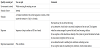
In the mapping between quality scenarios and use cases we distinguished between three cases:
- The quality scenario is an independent use case of its own. For example, responding to an 'emergency' signal arriving from a button pushed by a user, at any time;
- The quality scenario is a separate use case, extending an existing use case (with << extend >> dependency). For example, responding to a 'too close' signal arriving from a proximity sensor, while reversing the car;
- The quality scenario is a branch within an existing use case. For example, responding to an unapproved PIN, while the user is trying to withdraw money from an ATM.
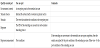
Table 3, 4 and table 5 below show the mapping between the parts of a quality scenario onto the corresponding parts of a use case, in these three cases. The Artifact part in all three cases is the system, as defined by the boundary frame in the use-case diagram, depending on the level of the use-case specification (i.e. system, sub-system, etc.). Therefore, we excluded it from the tables.
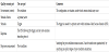
Using this mapping, quality scenarios (driven by non-functional requirements) can be incorporated into the functional scenarios, yielding a unified functional specification in use-case format. This is useful when the quality attributes and their specific responses are explicitly defined. Consider, for example, the UC#2: Navigation along Route use case. This use case already contains two responses to situations related to quality attributes, as follows:
- Step 7 of the MSS deals with the case where the location of the vehicle is off route – a violation of the Functional Completeness (under Functional Suitability) attribute. This condition (the stimulus), which comes spontaneously from the system itself (the stimulus source), implies, as a response, the invocation of an extending use case, namely UC#4: Calculate Route. If UC#4 will terminate normally, UC#2 will continue, However, if UC#4 will terminate abnormally (e.g. the route cannot be calculated), UC#2 will also terminate, leaving the post-condition ('car arrived at destination') unsatisfied. The success/fail result is the response measure.
- Branch A of UC#2: Navigate in Route responds to the violation of the Operability (under Usability) quality attribute (the driver has no control over the navigation process). In this case the response is implemented as a branch, where the exception point could be any step in the MSS, and the event causing the exception is the 'cancel' button pressed. It should be noted that while the driver deliberately pressed 'cancel' it causes the task to fail (i.e. violating the post-condition of arrival to destination).
The greater problem, however, arises when quality attributes are expressed only generally (e.g. "the system should be user-friendly") or even stay as unspoken expectations (e.g. the system is naturally expected to be user-friendly).
6.3 Applying quality attributes to use case scenarios
As already mentioned, (run-time) quality attributes should often be considered when undesired circumstances occur while the system is performing its tasks. It was also mentioned that while functional requirements define what the system has to do (i.e. apply functions in a sequence of steps), non-functional requirements define how well the system accomplishes its tasks. Therefore, we suggest to explicitly ask "How well?" questions about the functions used during a functional scenario5.
5"How well?" questions may also interpret as "Does anything can go wrong?", following a version of the famous Murphey's law – If anything can go wrong – it will!
As an example, consider again the MSS functional scenarios of UC#2: Navigation along Route. During the functional analysis process, as defined above, we defined the underlined functions and assigned them to functional components. Now we go back to investigate those functions in view of quality issues. For example, the function "enter 'navigation' mode" may be asked "is the driver aware of the mode change"? - a question which is related to the Usability quality attribute. Step 4 of the MSS of UC#2 applies the function "download map data from the server". The following question directly relates to Availability: "does the server respond within TBD seconds?".
"How well?" questions not only highlight specific situations to which a quality attribute applies, but rather help to reveal a related quality attributes, which were not explicitly specified or implied, as indirect consequence from other requirements. Suppose, in the same example, that there is a requirement for continuous/smooth display of the way in front of the driver. Missing map data may cause a delay in the display, which makes the navigation application unavailable to the driver for a while. Availability, in this case, is indirectly implied from a display issue. In many cases it is not easy to derive such a conclusion from the quality attribute itself; The question asked here referred to a specific situation and revealed immediately the availability issue.
Once the question asked, it points at a potential stimulus ('map data is not downloaded'). The stimulus source, in this case, is not external, but rather the system itself which indicates (e.g. by a timeout mechanism) that the server is unavailable. The natural response, then, is to generate a branch, which will be performed when this event occurs. Specifically, a new step (say 4.1) might be inserted between step 4 and 5 in the MSS as follows: "The system verifies that the map data is provided within TBD seconds". In addition, a new branch (say Branch B) should be added to the use case, such as an alternative (or an exception) from step 4.1 of the MSS: "The map data was not provided within TBD seconds".
However, this is just the beginning, since the following issues should now be considered:
- What should the system do now?
- Is this branch an alternative (i.e. leading to task success) or an exception (leading to task failure)?
- If new functionality is added, which components should be assigned the new functions?
The decision of what the system should do depends on the quality tactic chosen. Quality tactics are systematic actions taken to resolve quality attribute issues, and are proposed by several sources, such as [17,19,20] and more. Choosing the most appropriate tactic is at the discretion of the architecture team, based on considerations beyond this discussion. In the scope of this paper we assume that a tactic was chosen, and we elaborate only on the implications of this choice. One of the most popular availability tactics is redundancy, i.e. the system maintains a set of alternative resources, such that if any resource becomes unavailable, the system invokes an alternative resource to provide the required service.
Applying the redundancy tactics to our example means that the system should maintain multiple map data servers, and when one is unavailable it will reroute the service to a different one. If there are enough alternative servers, the eventual unavailability of all of them together is statistically negligible, so the system may go back to the MSS and continue the task. This means that the proposed branch is to be classified as 'alternative', since it prevented the fault (no data available) from becoming a failure (the driver will lose her way). The above is summarized in the new version of UC#2: Navigation along Route, as depicted in Figure 7 below, with the modification highlighted.
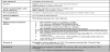
The new functions, namely "Verify that the map data is provided within TBD seconds" and "propose an alternative server", should now be assigned to functional components of the architecture. Moreover, the architecture might be modified in order to reflect the server redundancy. The architectural modifications and their implications are detailed next.
7. Architectural Modifications for Satisfying Quality Scenarios
7.1 Applying the new functionality to the functional architecture
The architecture is the platform that supports the system behaviour. Above we described the process of constructing an architecture on the basis of the functional specifications. As we saw in the previous Section, resolving quality attribute issues may impose additional functionality on the system. Since the functionality is directed to the architecture by assigning the new functions to functional components, the architecture should be re-addressed, and if the current set of functional components cannot (or should not) support the new functions, new components (and their interfaces) should be added. Moreover, the chosen tactics (e.g. resource redundancy) may impose further changes to the structural architecture. The new functionality, together with the modified set of components may also require modifications to the system's behaviour (i.e. the interactions of components between each other or with the external environment). This means that the entire architecture should now be modified accordingly. We demonstrate the architecture modification process on the basis of our CNS case study.
The first step is the functional assignment. Consider the set of functional components comprising the CNS functional architecture shown in Figure 4. The new function "Verify that the map data is provided within TBD seconds" may be naturally assigned to the Navigation App component, which, while sending a map request to the Map Service component may set a watchdog, which will track the request and will raise a timeout flag when the request is not answered within the allocated time. Nevertheless, the "propose an alternative server" function cannot be easily assigned to the Map Services component, since, in the current architecture, this component comprises a single source of data, without redundancy. If this component is now duplicated, proposing an alternative server should be allocated to a different component, who "knows" all the Map Services. A common architecture pattern for such a situation is the Broker pattern [21]. A broker is a mediator between service consumers and service providers. The broker does not provide any service by its own, but it maintains a list of registered service providers. When a consumer needs a service, it requests the broker, who provides the address of one of its registered service providers. The consumer can now connect directly to this provider and request the service. This is naturally analogous to a taxi dispatch station, who connects drivers (trip providers) to clients (trip consumers).
Thus, the next step is to replace the single Map Services component by a single Map Broker and a set of multiple Map Services components. This implies that the Navigation App component will now have to possess an additional (required) interface to connect to the (provided) interface of the Map Broker, in order to request a map service. Once the Map Broker provides the address of a selected Map Services, the Navigation App may approach it using the existing Map Requests interface pair. The resulted modified architecture is shown in Figure 8 below.
It should be noted that the change from a single server to multiple servers, mediated by a broker, requires also a change in the binding policy: The binding in the original functional architecture ( Figure 4), between the Navigation App component and the (single) Map Services component is static, meaning that the application always knows that server. When multiple servers are used (as depicted in the modified architecture of Figure 8), the binding between an application and a server becomes dynamic, i.e. may change over time. However, the binding of the (single) broker to the application now becomes static. Moreover, the Navigation App component must now have a new required interface (to the Map Broker component) in addition to the one it already has (to a Map Services component).
From the behavioral point of view, the implementation of use case #2: Navigate along Route, as described in Figure 6, has to be changed by adding the Map Broker component and the "swapping" mechanism enabling the Navigation App component to request alternative Map Services component and to connect to it. Figure 9 below shows a part of the modified sequence diagram of Figure 6 - an elaboration of the "download_from_server" option ('opt' fragment) that comes after the Navigation App's unsuccessful attempt to retrieve a relevant map area within its locally-available map data: In order to indicate an unresponsive Map Services component (named MS1) a watchdog is invoked in parallel to the map data request. A 'timeout' flag raised by the watchdog indicates the unresponsiveness. In this case a request for an alternative Map Services component is issued to the broker, which returns the address of another Map Services component (named MS2). Then the Navigation App component may approach MS2 and download the requested map data.
7.2 Further implications of the architectural modifications
In the previous Subsection we proposed architectural changes implied by considering an Availability issue, which were based upon two architectural decisions:
- Using multiple servers (i.e. by applying the Redundancy tactics);
- Changing the binding of an application to a map server from static to dynamic (by applying the Broker architecture pattern).
- We have also demonstrated these changes by means of UML models.
7.3 Modifications to the physical architecture
In the physical architecture shown in Figure 1, we assumed that the map data DB resides in a physically separate node (a server). When a broker is introduced, it should be decided where to locate it, where the possibilities are: (a) in the Smartphone node, (b) in the Navigation Server node, (c) in a (new) separate node. Such decision immediately requires new considerations about the physical links, which might lead to physical architecture change.
7.4 Added functionality
On top of the functionality added to use case #2: Navigate along Route (as shown in Figure 7), the broker mechanism, for example, requires that Map Services components will be able to register/ unregister at the broker as service provision candidates. It is likely that a new use case ("Register/Unregister") is to be added to the usecase diagram of Figure 2. In addition, we may want the broker to propose only "live" servers, thus enabling it to check a server's status before proposing it as an alternative candidate. This might be added as additional action/condition to the use-case specification (and, consequently, to the sequence diagram). Note that corresponding interfaces (between the Map Broker and Map Services components), to support these two functionalities, has already been considered in the modified architecture of Figure 8.
7.5 Additional quality scenarios
In the original architecture, the single Map Services component was a single point of failure, thus giving rise to an Availability scenario caused by the unresponsiveness of the server. When the component was duplicated, and a Map Broker introduced as a mediator, the availability of the server was resolved, but caused the broker to become a single point of failure, which might raise a new Availability scenario, caused by unresponsiveness of the broker. Although this issue may be revealed by applying a "How well?" question to the "propose an alternative server" function in Branch B of the modified use case, the considerations, as well as the proposed tactics, may be different this time. The phenomenon that "every solution causes new problems" will be discussed in the last Section of the paper.
8. Summary and Conclusions
In this paper we suggested an approach to resolve run-time quality attribute issues in software-intensive systems, whether expressed explicitly (as non-functional requirements) or implicitly (as stakeholder expectations about the quality of the system). Our approach is based upon substituting quality attributes by quality scenarios, thus providing functional solutions to non-functional issues. We assume that run-time quality attribute violations usually emerge while the system is operating (i.e. applies its functionality), and therefore such faults can be indicated in the functional scenarios, by applying "How well?" questions, i.e. trying to identify what can go wrong during this operation. As a response, we introduce new functionality, in attempt to prevent the fault from becoming a failure of the entire task. Presuming that an architecture already exists, we apply the new functionality to it, with the possible use of architecture patterns, modifying the architecture accordingly.
In the following we summarize the proposed two-phase process, as detailed and demonstrated in the paper, using UML modeling. We refer to the architecture in its four views, as mentioned in the above.
-
Phase 1: Construct an initial functional architecture
- Construct a Use Case Model (Use-case Diagram + Use-case Specifications) from the functional requirements;
- Identify the functions comprising the functional scenarios (MSS + branches);
- Propose functional components and assign to them the functions identified in step 1.2;
- Implement the Use-case specifications of step 1.1 as interactions between the components proposed in step 1.3, constructing the Interaction View as a Sequence Diagram;
- Derive the provided and required interfaces for each functional component from the interaction needs of step 1.4, constructing the Functional Architecture as a Component Diagram;
- If applicable, obtain the Physical Architecture of the entire system as a Deployment Diagram and combine it with the Functional Architecture of step 1.5 into a Combined Architecture as a Composite Diagram.
-
Phase 2: Consider quality attributes and modify the architecture
accordingly
- Apply "How well?" questions to the functions identified in step 1.2 (i.e. try to anticipate faults that may happen when the function is performed);
- Relate each fault to a quality attribute (or sub-attribute) and choose a response tactic;
- Add the response to the Use-case Model as new functional scenarios, my means of either (a) a new use case, (b) an extending use case of the current one or (c) a branch in the current use case;
- Identify the newly added functions implied from step 2.3;
- Assign those functions to existing functional components, or propose new ones;
- Modify the Interaction View (the Sequence Diagrams) by consequently implementing the scenario modifications made in step 2.3;
- Modify the Functional Architecture (the Component Diagram) in correspondence with the modifications of step 2.6;
- If applicable, modify the Physical Architecture (the Deployment Diagram) and the Combined Architecture (the Composite Diagram) accordingly;
- Repeat steps 2.1-2.8 until reaching a satisfiable architecture (subject to the applicable architecture assessment criteria).
Although the process described above is systematic, and may lead to "acceptable" architecture, it is not simple and requires considerable effort of skilled software and system architects. It should also be noted that the term "acceptable architecture" is rather subjective, depending upon other considerations, such as stakeholder satisfaction, schedule, budget, etc. On the other hand, since the process is model-based, a number of resulting architectures may be compared and evaluated conveniently.
In the case-study described throughout the paper we demonstrated the process over a single issue (map server availability). As discussed above, an architectural modification may yield to additional quality issues, repeatedly. However, addressing a big number of quality issues at one iteration may complicate the process significantly. Therefore, the number of quality issues resolved at any one time should be adapted to the capacity and skills of the architects, as well as to stakeholders' priorities.
9. Further Research
The approach proposed in this paper needs further practical validation. Parts of it were already been applied at model-based software engineering courses, delivered by the author, both at undergraduate and graduate levels, and proved to be applicable. As mentioned, the quality of the resulted architecture is subjective, but further research may attempt to apply more objective criteria.
Another research direction might be to automate the process. However, since the application of it is based on human knowledge and decision-making it is inevitable to assume that such automation must be addressed using artificial intelligence techniques. One of the most significant issues throughout the process is the consistency among the various views of the architecture, although the systematic application of the process, i.e. deriving new models from other models, is intended to preserving consistency "on the fly".
In this paper we used structured text (use-case specification) to formalize functional scenarios. There are other models used to describe scenarios, such as UML Activity Diagrams. Since the scenario model is used here as the source where functions are identified, it appears that Activities or Actions of an Activity Diagram might serve the same purpose. We intend to explore this issue in the future.
The discussion in this paper was excluded to only run-time quality attributes. In fact, non-run-time (design-time) attributes apply to the development process rather than to the functionality of the system. Modifiability (under Maintainability), for example, is violated in the event that a development cycle fails to satisfy a newly introduced requirements, since one of its components cannot be changed. In order to prevent this fault from becoming a failure (i.e. a new version cannot be released) a change to the development process may be applied, suggesting to develop a modifiable (generic) component instead. Thus, the same process may be applied to nonrun- time attributes, given that the development process is described as a functional scenario (for the "development team" system). This might lead to another research direction, dealing with development processes rather than with system operation.
Competing Interests
The author declare that there is no competing interests regarding the publication of this article.