


1. Introduction
Nowadays, the number of vehicles is rapidly increasing in a lot of developing countries including Myanmar. At the same time, the vehicle theft has become a serious issue in the societies. According to the survey in 1st October 2015 in Myanmar Times News, the number of vehicles on roads has been nearly doubled since 2011. It is jumping from 2,363,947 to 5,077,699 due to the Ministry of Transportation, Myanmar [1]. Then, a Vehicle Anti-theft Tracking (VAT) system that can be installed into a vehicle with a low cost at any time, is strongly demanded, since a conventional VAT system is very expensive and is usually installed into a luxury car when it is produced.
Basically, there are three types of VAT systems, namely, the cellular tracking system, the wireless passive tracking system, and the satellitebased tracking system [2]. A practical VAT system is developed based on either of them. The cellular tracking system uses cellular phones to transmit fleet location information. In the wireless passive tracking system, users have to pay one time upon purchase and installation of the device. The main disadvantage is accessibility where data can only be accessed when the vehicle is home. The satellite based tracking system can give detailed reporting and real-time updates on company fleets even in places where there is no cellular phone coverage, though it is very expensive with a monthly service fee.
In [3], the school bus tracking system is developed for the safety of school children, where it compares the current route with the predefined route. If they are different, an alarm is triggered. Unfortunately, this system cannot show the routes that the vehicle travelled over a given time interval.
In [4], the vehicle tracking system was proposed to track the vehicles in a city using RFID (Radio Frequency Identifier). However, the RFID tag needs to be assembled on the vehicle, and RFID readers must be installed on every junction of roads. Besides, the proper information of the vehicle cannot be received when the RFID range is over. Thus, this system is too costly.
In [5], a vehicle theft alarming system was developed. It triggers the alarm when the door lock is opened in the improper manner or the key is inserted without the authority of the owner. They are detected by attached sensors on the doors or key entry of the vehicle. However, it is reported that 96% of people are unaware of the alarm. Moreover, the sensors can notify only the information of the vehicle theft. Besides, attaching sensors in a vehicle costs a lot, and makes it difficult to use this system at an arbitrary time.
In [6], a vehicle theft detecting and tracking system was proposed. The locking system is also installed in the vehicle to lock engine motor. When the theft is identified, the responsible person sends SMS to the microcontroller and then the engine motor is stopped. To restart the vehicle, the authorized person restarts the vehicle and opens the door. This system is more secured, reliable and low cost. However, it is needed to have a connection between the car engine system and the vehicle theft detecting and tracking system.
On the one hand, the Internet of Things (IoT) has come out as a popular technology changing the concept of “connecting people” to “connecting things”. The IoT provides a network of sensors, actuators, machines, and home appliances. They are embedded with computing devices and software, which enable these things to be connected with each other and exchange data over Internet. A variety of low-cost devices and cloud platforms for the IoT have become available.
In this paper, we propose a very low-cost personal use VAT system using the IoT cloud platform. This system allows people in developing countries to be easily installed into their vehicles at any time. This system has the following features: (1) the vehicle theft is detected using an Arduino-connected GPS (Global Positioning System) module, (2) the alarm message is sent to the mobile phone of the vehicle owner by the SMS (Short Message Service) on GSM (Global System for Mobile Communications), (3) the conditions of GPS/GSM modules are always monitored where the alarm is sent to the owner if they are not live, and (4) the location data of the vehicle is periodically stored in the IoT cloud platform called ThingSpeak. We implement this system and confirm the correctness of the designed functions through trial applications.
The rest of the paper is organized as follows. Sections 2 and 3 present the design and the implementation of the proposed system respectively. Section 4 shows preliminary evaluations of the system. Section 5 concludes this paper with future works.
2. System Design
In this section, we present the design of the proposed personal use VAT system.
2.1 Overview
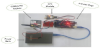
The proposed system is composed of the theft detection device at a vehicle, the cloud IoT platform in the Internet, and the mobile phone at a vehicle owner. Figure 1 illustrates the overview of the system. The theft detection device consists of a GSM module, a GPS module, and a microcontroller. For the microcontroller, Arduino Mega is adopted, where Arduino IDE and Android Studio are used in developing software for this device. They are available at very low costs. For the IoT platform, ThingSpeak Server is adopted where the basic function can be used free.
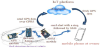
The GPS module at the theft detection device is used to detect the vehicle theft. If the vehicle location that is monitored by the GPS is changed by more than the threshold without the consent of the owner, it is regarded as the theft. The GSM module is used to upload this vehicle location data to the server over the Internet periodically, and transmit the theft alarm message to the mobile phone of the owner using the SMS.
2.2 Hardware description
The details of the adopted hardware are described as follows.
2.2.1 Microcontroller
Arduino Mega 2560 is used as the microcontroller for this system. Arduino Mega 2560 is a microcontroller board based on the ATmega2560. It has 54 digital input/output pins (of which 15 can be used as PWM outputs), 16 analog inputs, 4 UARTs (hardware serial ports), a 16 MHz crystal oscillator, a USB connection, a power jack, an ICSP header, and a reset button. It contains everything needed to support the microcontroller; simply connects it to a computer with a USB cable or power it with a AC-to-DC adapter or battery to get started.
2.2.2 GPS module
Ublox Neo 7N-0-002 GPS module is used in this system. This module has an external antenna and built-in EEPROM. It requires a power supply of 3V to 5V and a default baud rate of 9600 bps. It works with NMEA sentences. Neo 7N has the data logging feature, which enables continuous storage of position, velocity and time information to an internal 16Mbit SQI FLASH memory. The GPS module receives data from the GPS satellites and calculates the module’s geographical location. Once the module is powered, National Marine Electronics Association (NMEA) sentence is sent out of a serial transmit pin at default baud rate (9600bps).
2.2.3 GSM module
SIM900A GSM module produced from SIMCOM is used in this system. It works on the frequencies of 900 and 1800 MHz where SIM900A can search these two bands automatically. The frequency bands can also be set by AT command. The baud rate is configurable from 1200-115200 bps through AT command. The baud rate of 9600 bps is used for the GSM module in the theft detection device. Using the internal TCP/IP stack, this module can be connected to the Internet via GPRS (General Packet Radio Service). SIM900A is an ultra-compact and reliable wireless module. This is a complete GSM/GPRS module in a SMT type and designed with very powerful single-chip processor integrating AMR926EJ-S core and is very costeffective.
2.3 Software description
The details of the adopted software are described as follows.
2.3.1 Thingspeak server
ThingSpeak server is an open data platform and API for Internet of Things that allows data to be collected, stored, analyzed and visualized. ThingSpeak provides instant visualizations of data posted from the devices to ThingSpeak. With the ability to execute MATLAB code in ThingSpeak, online analysis and processing of the data can be performed. ThingSpeak is often used for prototyping and proof of concept IoT systems that require analytics. ThingSpeak allows users to aggregate, visualize and analyze live data streams in the cloud. To store data in the server, it is needed to create ThingSpeak account first and create a channel in that account. Then the data that comes from things can be viewed in the fields of the channel.
2.3.2 Arduino IDE
For the communication between the microcontroller and the modules and for sending and receiving vehicle location information between the microcontroller and the server, the microcontroller and the modules are programmed by the Arduino IDE software. The Arduino integrated development environment is a cross-platform application for Windows, Mac OS, and Linux that is written in the programming language Java.
2.3.3 Android studio
A mobile Android application is developed to track the vehicle location and the route the vehicle travelled. Android Studio is used for developing this application. It is the official integrated development environment for Google's Android operating system, built on JetBrains' IntelliJ IDEA software and designed specifically for Android development.
2.4 IoT architecture description
The IoT architecture of the proposed system is discussed.
2.4.1 Five layer IoT architecture
The IoT extends the Internet connectivity beyond traditional devices like computers, smartphones, and tablets, to a diverse range of devices and daily things that utilize the embedded technology to communicate and interact with external environments via the Internet. The main functions of the IoT are to collect data and transform it into useful information. Based on the TCP/IP model, the basic IoT architecture is the three-layer one. It includes the perception layer, the network layer, and the application layer [6].
However, the three-layer architecture is insufficient for research on the IoT, and hence, is extended to the five-layer architecture, shown in Figure 2 [6]. The perception layer and application layer remain, while the network layer is divided into the transport layer and the processing layer. The business layer is added as the final layer.
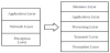
The perception layer gathers the information from the environment and identifies the objects. The information from the perception layer is transferred to the processing layer via the transport layer. The processing layer stores, processes, and analyzes the transferred data. The application layer delivers the specific services to the users. The business layer manages the whole IoT system.
2.4.2 IoT architecture of proposes system
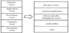
From the perspective of the IoT five-layer architecture, the GPS module works in the perception layer, where it collects the location information of the vehicle. The GSM module sends the alarm message to the owner’s mobile phone by the SMS, and transfers data back and forth between the ThingSpeak server and the microcontroller by using the GPRS. Thus, the GSM/GPRS module is responsible for the transport layer. The location information detected by the GPS module is analyzed at the microcontroller and is stored in the ThingSpeak server. Thus, the microcontroller and the ThingSpeak server are responsible for the processing layer. The Android application is developed for the user requirement. Thus, it works in the application layer. The business layer is not included in this system, because it is designed for personal use.
3. Implementation
In this section, we present the implementations of the proposed system.
3.1 Theft detection logic
In this system, the vehicle theft is detected by comparing the distance between the parked position and the current position with the given threshold. This distance d is calculated by using the Haversine formula. From the latitude and longitude values of these two positions, the distance is calculated by:
where ∅1 and ∅2 represent the latitude of the parked position and
that of the current position, Δ∅ does the difference of the latitudes,
Δ
Then, the distance is compared with the given threshold D (= 5 feet in this paper). If d ≥ D, it is regarded as the vehicle theft.
3.2 Function Flow
In the proposed system, the theft detection device is placed at the proper position in the vehicle. Then, the GSM module of this device is initialized by activating the SIM card inside the module and connecting it to the Internet over the GPRS.
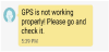
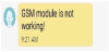
The power supply is given to make the device work. The GPS and GSM modules are firstly checked whether they are working correctly or not. The GPS module will not work if it does not have the clear line of sight to satellites. Also, the GSM module will not work if its antenna cannot receive the proper signal from a base station. If either one of the modules is not working properly, the system will send the message by SMS to the owner’s mobile phone, stating that the module is not working properly.
When both modules are working properly, the GPS module will continuously receive the location information of the vehicle from satellites as long as the power is on. The collected location information is sent out from the transmission pin of the GPS to the reception pin of the microcontroller as the NMEA sentences. The NMEA sentences are parsed into useful values by using the functions provided in the TinyGPSPlus library. The parsing is simply removing the chunks of data from the NMEA sentences. The Arduino Mega microcontroller sends them to ThingSpeak server every 15 seconds using the TCP/ IP protocol over the GPRS. ThingSpeak server then stores the data in ThingSpeak channel. The vehicle location information includes the latitude, the longitude, the speed, the number of detecting satellites, the accuracy, and the direction.
Then, the distance between the last two locations is calculated using the Haversine formula. When the vehicle is parked, the location will remain at the same one until the owner moves it. However, if the vehicle moves from the parked position, the location change will occur between the parked position and the current position. If the location change distance between these last two positions is greater than or equal to 5 feet, the alarm message will be sent to the owner’s mobile phone by the SMS indicating that the vehicle is being stolen.
Also, there is a switch between parking mode and driving mode. When the owner can set the car to the parking mode when it is parked. As soon as the vehicle starts moving because of the thief, the switch will release to the driving mode. Then the owner can know immediately that his car is being stolen and he can call the police.
By using the Android application, the owner can know the current location as well as the route information of the vehicle at the given interval. The Android application sends the URL to ThingSpeak server along with the ThingSpeak channel number and the API key, fetches the location information from ThingSpeak server, and shows the required information of the current location and the route information of the vehicle on Google Map. Thus, the owner can track the vehicle remotely in real time. The overall function flow of the system is explained in Figure 4.
3.3 Device implementation
The GPS module and the GSM module are connected to the Arduino Mega microcontroller, where they have the common ground. They are powered from the power bank or the battery. According to the datasheet of the Ublox GPS module, the maximum working current is 40mA at the normal operating condition. The GSM module needs about five seconds per minute for transmitting data by spending 200 mA, which would give 24 mA on average. The GSM module will take 50 mA. The DC current per I/O pin in Arduino Mega is 20 mA. By summing up the total current, the estimated current drawn of the device is 134 mA (= 40+24+50+20).
The adopted power bank in the system can supply the battery capacity of 13,000mAh. The battery life is calculated based on the current rating in Milliampere (mA) and the capacity of the battery in Milliampere Hours (mAh). The ratio of the battery capacity and the multiplication of the consuming rate and the device consumption gives the battery life. When it is assumed that the consuming rate is 0.7, the power bank will last around 82 hours. The rate 0.7 makes allowances for external factors which can affect the battery life. The more power the power bank can supply, the longer the device will last.
The program for the device is written in C, and is uploaded to the Arduino Mega microcontroller by using the Arduino IDE. The device implementation in the system is shown in Figure 5.
3.4 GPS data format
The GPS data is displayed in different message formats over a serial interface. Nearly all the GPS receivers output the NMEA data. The NMEA standard is formatted in lines of data called sentences, such as $GPGGA, $GPGSA, $GPGSV, $GPGLL, $GPRMC, and $GPGTV. In the system, the location data of the vehicle is transferred from the GPS module to the microcontroller by the following $GPGGA sentence format:
$GPGGA,235317.000,4003.9039,N,10512.5793,W,1,08,1.6,1577 .9,M,-20.7,M,,0000*5F
This $GPGGA format example will be explained in detail as:
- Time: 235317.000 indicates 23 (hour), 53 (minute), and 17.000 (second) in the Greenwich mean time.
- Longitude: 4003.9040,N does the longitude of 4,003 (degree by decimal), 9040 (minute), and north.
- Latitude: 10512.5792,W does the latitude of 10,512 (degrees. decimal), 5,792 (minute), and west.
- Number of satellites seen: 8
- Altitude: 1,577 meters
3.5 ThingSpeak server connection
In the system, the location data of the vehicle is transferred from the Arduino Mega microcontroller to ThingSpeak server. The TCP connection from the microcontroller to ThingSpeak server is started by giving the host name and the port of ThingSpeak server, which becomes possible by initiating the “AT+CIPSART” command. When the GPRS is connected to the ThingSpeak server, the data must be sent. Here, the latitude, the longitude, the number of satellites, the speed, the accuracy, the direction, and the location message are sent to the ThingSpeak server. Since the data is stored in the fields of the channel of ThingSpeak server, the channel API key is also needed. The data is sent in the String format to ThingSpeak channel by using the “AT+CIPSEND” command. The commands for sending the data from the microcontroller to ThingSpeak server are shown as follows:
Starting TCP connection:
"AT+CIPSTART=\"TCP\",\""+HOST+"\","+PORT,15,"CONNECT"
Data to send:
String getData = "GET /update?api_key="+ChannelAPI+"&"+"fiel d1"+"="+String(lat,6)+"&field2="+String(lon,6)+"&field3="+String(s atellite)+"&field4="+String(speed)+"&field5="+String(accuracy)+"&f ield6="+String(direction)+"&field7="+String(locationMsg);
Sending data:
"AT+CIPSEND="+String(getData.length()+4),4,">"
3.6 Cost estimation
Here, we estimate the cost in Myanmar currency required to introduce and operate the proposed system. For the introduction, the GPS module costs 22,000 Kyats, the GSM module costs 15,000 Kyats, and Arduino Mega costs 16,000 Kyats. When the cost of wires is included, the overall device costs around 55,000 Kyats. For the operation, the SIM cards inside the GSM module costs about 6 Kyats/MB to connect to the Internet and send SMS messages and each message costs 25 Kyats. The free option is used for ThingSpeak. Thus, the total cost is not high and is affordable for many people in Myanmar.
4. Experimental Result in Android Application
In this section, we evaluate the proposed VAT system.
4.1 Experiment setting
The implemented theft detection device for the VAT system was installed on a motorbike as a vehicle. Then, this motorbike moved from “Mann Thazin Hostel” in Mandalay Technological University to “Quality Food Restaurant” in Patheingyi, which has around 4.5 km distance. After the vehicle reached the destination, the periodical location data was downloaded from ThingSpeak server to the Android mobile phone of one author, and the current location and the route information were shown at the mobile phone display on Google Map. The application software to view the current location and route information is developed for the mobile phone.
4.2 Experiment results
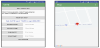
The current location can be viewed at any time, as shown in Figure 6. To retrieve the route information of the vehicle, the time interval the starting date/time, and the ending date/time need to be input from the user interface. Then, the Android application will fetch the data between the specified period from the server, connect the location points using Polyline, and show the route on Google Map, as shown in Figure 7. Thus, the vehicle owner can view the current location as well as the route information of the vehicle from any place in real time.
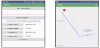
In the current implementation, the system can store the location data in ThingSpeak server every 15 seconds, because the free version is used. As a result, some parts of the moved path are shown by straight lines, as in Figure 7.
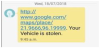
The system will send corresponding alarm messages by the SMS if the vehicle is theft, or the GPS/GSM module is not working properly, as shown in Figures 8-10.
5. Discussion
The proposed VAT system is integrated with ThingSpeak server and the Android application. The Android application is very simple to use. Even if the vehicle owner has little IT knowledge, he/she can use it. When the GPS or GSM module is not working properly, the owner can know it from the alarm message by the SMS immediately. The system is small and very cost effective. Thus, it can be installed in any kind of vehicle including a car, a motorbike, and a bicycle.
6. Conclusion
This paper presented the very low-cost and personal use vehicle anti-theft tracking system using the cloud IoT platform called ThingSpeak. The anti-theft device for a vehicle is implemented with the Arduino microcontroller, the GPS module, and the GSM module. The alarm messages are sent to the mobile phone by the SMS. The correctness of the implemented functions was confirmed through trial applications. The future works include the extension of Android applications for vehicle owner services, the durability test of the device, and the evaluation through the long term use.
Competing Interests
The authors declare that they have no competing interests.