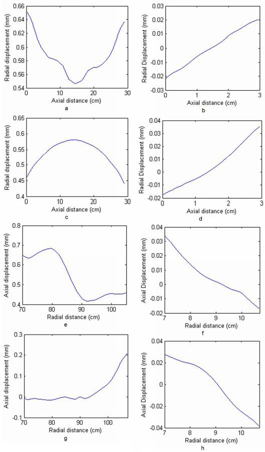
Figure 12: Displacements along vertical and horizontal lines. On the left-hand side plots are shown for the real gear, on the right-hand side for the lab-scale gear. a) and b) Radial displacement along line IV2 (inside). c) and d) Radial displacements along line OV2 (outside). e) and f) Axial displacement along line BH2. (bottom). g) and h) Axial displacement along line TH2 (top).