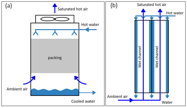
Figure 3:
Schematic diagrams (a) General cooling tower scheme. (b) Conventional cooling tower. Reproduced from
[5
,
6]
.